Computer Networks


Syllabus

Screenshot 2025-01-02 at 1.12.06 PM.png


Unit 1

Computer Networks

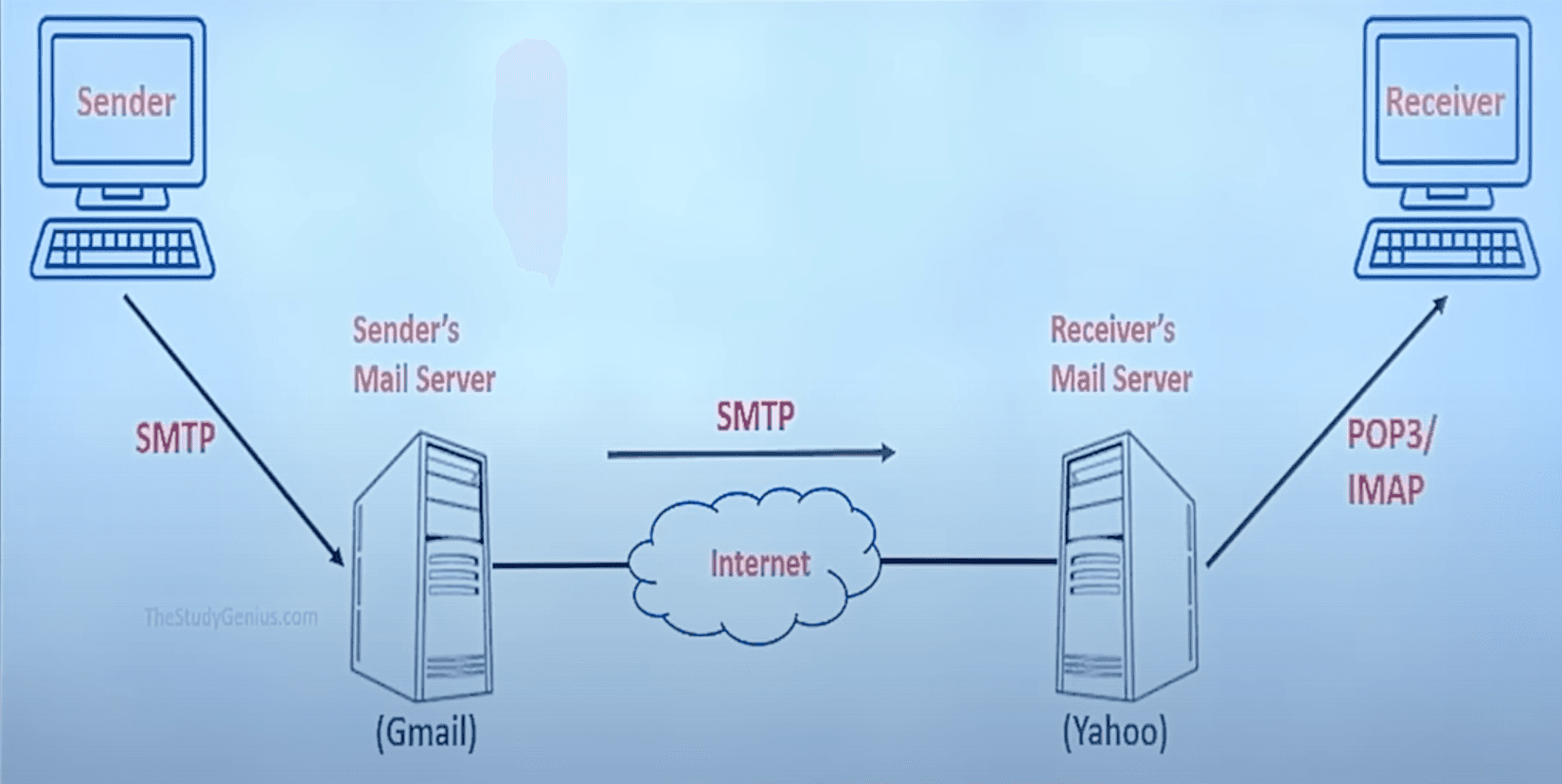
It is a telecommunication network, which allows autonomous digital devices (nodes) to exchange data between each other using either wired or wireless connections to share resources (hardware or software) interconnected by a single technology e.g. internet.

Internet means empowerment

Goals of Computer Networks

  1. Facilitating Communication: Swift communication between individuals and organizations. Eg: video conferencing, emails, sms, etc.
  2. Resource Sharing: Allows users to share hardware and software resources.
  3. Data Storage and Access: Centralized storage system that allow data access from any connected device. Easy backup and recovery.
  4. Cost Efficiency: Reduces cost by sharing resources and avoiding duplication of h/w and s/w.
  5. Reliability and Redundancy: Enhanced reliability though alternate paths and redundant systems in case of failure.

Applications of Computer Networks

  1. Business and Commerce: banking, stock trading, e-commerce, etc. Remote working and global collaboration.
  2. Education: E-learning, online exams, virtual classrooms. Research and more knowledge sharing.
  3. Healthcare: Telemedicine, electronic health records, remote patient monitoring, etc.
  4. Government Services: Online public services, secure communication between agencies.
  5. Entertainment: Online gaming, streaming services, social media, etc.
  6. Scientific Research: Worldwide data sharing and research collaboration.
  7. Travel: GPS, online booking, etc.

Data Communication

Exchange of data between two devices via some transmission medium.

Data communication system has five components - Pasted image 20250102133339.png

  1. Message: Information to be communicated.
  2. Sender: Device that sends the message.
  3. Receiver: Device that receives the message.
  4. Transmission Medium: Physical path by which message travels.
  5. Protocol: Rules (including Syntax, Semantics, Timing, De facto, De jure).

Transmission Mode

Data flow between two systems can be categorized into three types -

  1. Simple Mode:
    • Communication is unidirectional.
    • One devices always sends, while other one only receives.
    • Can use entire capacity of channel to send data in one direction.
    • Eg: Broadcast radio.
  2. Half Duplex:
    • Each station can both transmit and receive, but not at the same time.
    • One must receive when the other is sending, and vice versa.
    • Entire capacity of a channel is taken over by whichever of the two devices is transmitting at the time.
    • Eg: Walkie-talkies.
  3. Full Duplex:
    • Both stations can transmit and receive at the same time.
    • Basically just two half duplex connections working closely.
    • Capacity of channel must be divided into two directions.
    • Eg: Telephone

Network Criteria

  1. Delivery and Accuracy: Must deliver error-free data to correct destination.
  2. Performance: Transit time, response time, number of users, type of transmission medium, capabilities of connected hardware's and efficiency of software.
  3. Reliability: Low frequency of failure and quick to resolve.
  4. Security: Protection from unauthorized access and damage and development.

Types of Connection

  • Point to Point: Provides a dedicated link between two devices.
  • Multipoint: (also called multidrop) Connection in which more than two specific devices share a single link.

Screenshot 2025-01-02 at 5.35.58 PM.png


Physical Topology

Refers to the way in which a network is laid out physically. Topology of a network is the geometric representation of relationship of all the links and linking devices to one another.

Pasted image 20250102174423.png

Mesh Topology

Every device has a dedicated point-to-point link to every other device. We need,

n(n1)2\frac{n(n - 1)}{2}

duplex-mode links, where nn is the number of nodes.

AdvantagesDisadvantages
Traffic handlingInstallation and reconnection are difficult
RobustSheer bulk of wiring is expensive
Privacy and security
Easy fault identification and isolation

Star Topology

Each device has a dedicated point-to-point link only to a central controller, usually called a hub. The devices are not directly linked to one another.

The controller acts as an exchange.

AdvantagesDisadvantages
Less expensive than meshDependency of entire topology on a single point
Easy to install and reconfigureMore cables?
Robust (independent links)
Easy fault identification and isolation

Bus Topology

  • One long cable acts as a backbone to link all devices in a network. (Multipoint)
  • Nodes are connected to the bus cable by drop lines and taps.
  • A drop line is a connection running between the device and the main cable.
  • A tap is a connector that either splices into the main cable or punctures the sheathing of a cable to create a contact with the metallic core.
AdvantagesDisadvantages
Ease of installationDifficult reconnection and fault isolation
Uses less cablesDifficult to add new devices
Low security and privacy
A fault in bus cables stops all transmission

Ring Topology

  • In a ring topology, each device has a dedicated point-to-point connection with the two devices on either side of it.
  • A signal is passed along the ring in one direction, from device to device, until it reaches its destination. Each device in the ring incorporates a repeater.
  • When a device receives a signal intended for another device, its repeater regenerates the bits and passes them along.
AdvantagesDisadvantages
Easy to install and reconfigureA break in ring can disable entire network
Fault isolation is simplified

Local Area Network (LAN)

  • Usually limited to a few kilometers of area.
  • Privately owned or office or entire building.

Metropolitan Area Network (MAN)

  • MAN is of size between LAN and WAN.
  • City

Wide Area Network (WAN)

  • WAN is made of all the networks in a larger area.
  • State

OSI Model

Open System Interconnection

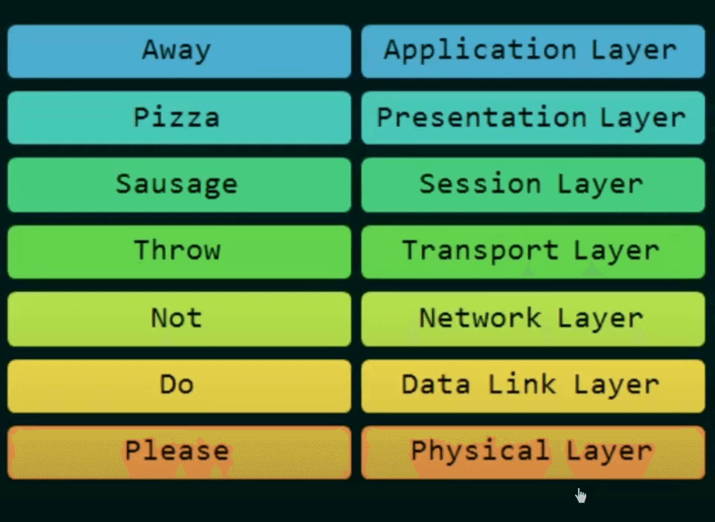
  • It is a model for understanding and designing a network architecture that is flexible, robust, and interoperable (exchange data b/w diff machines of diff types or OS).
  • Developed by ISO (International Standards Organization)
  • The OSI Model is not a protocol. It is only a guideline.
  • The purpose of the OSI model is to show how to facilitate communication between different systems without requiring changes to the logic of the underlying hardware and software.
  • The OSI Model was never fully implemented.

Screenshot 2024-11-22 at 3.39.13 PM.png

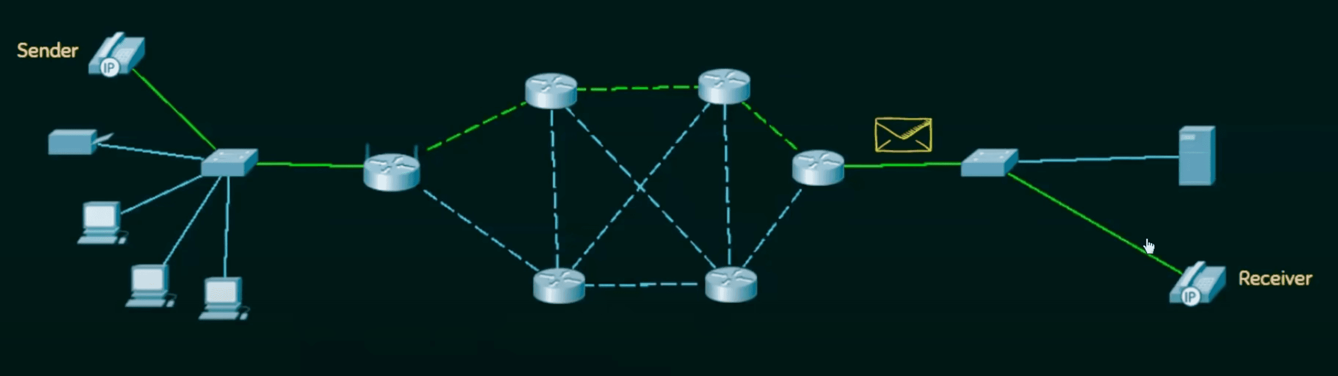
  • First data is encapsulated from Application Layer -> Physical Layer
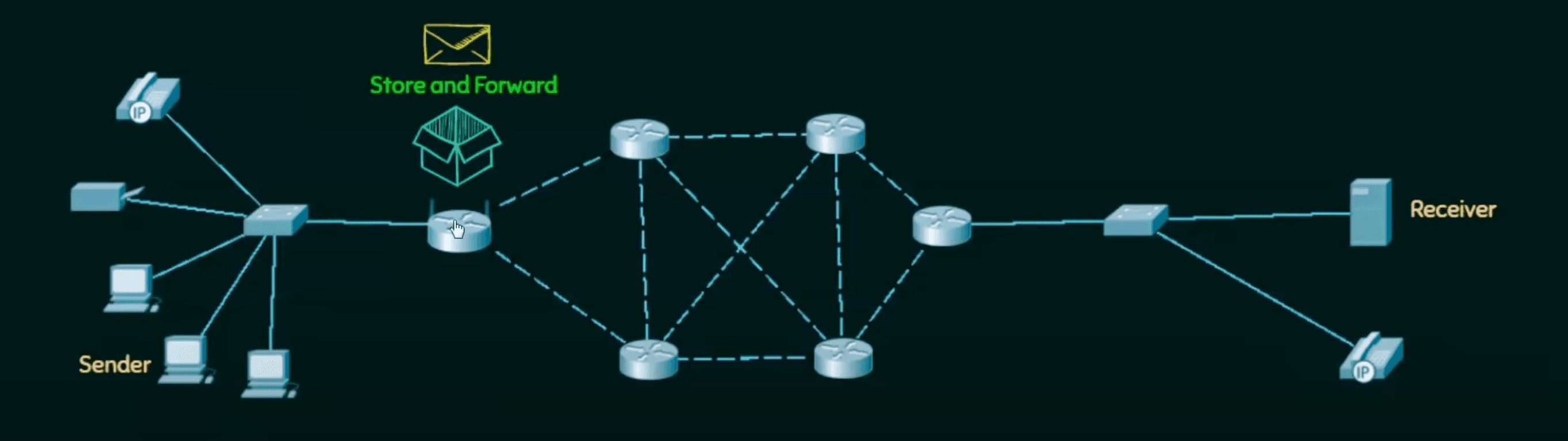
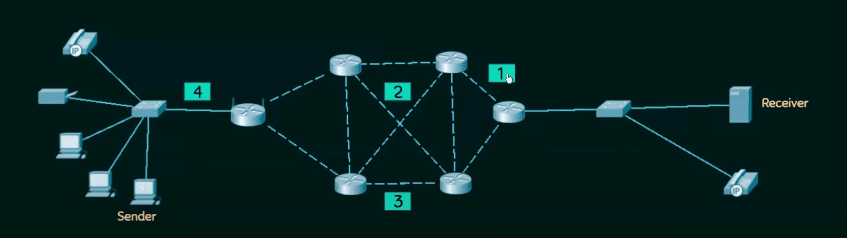
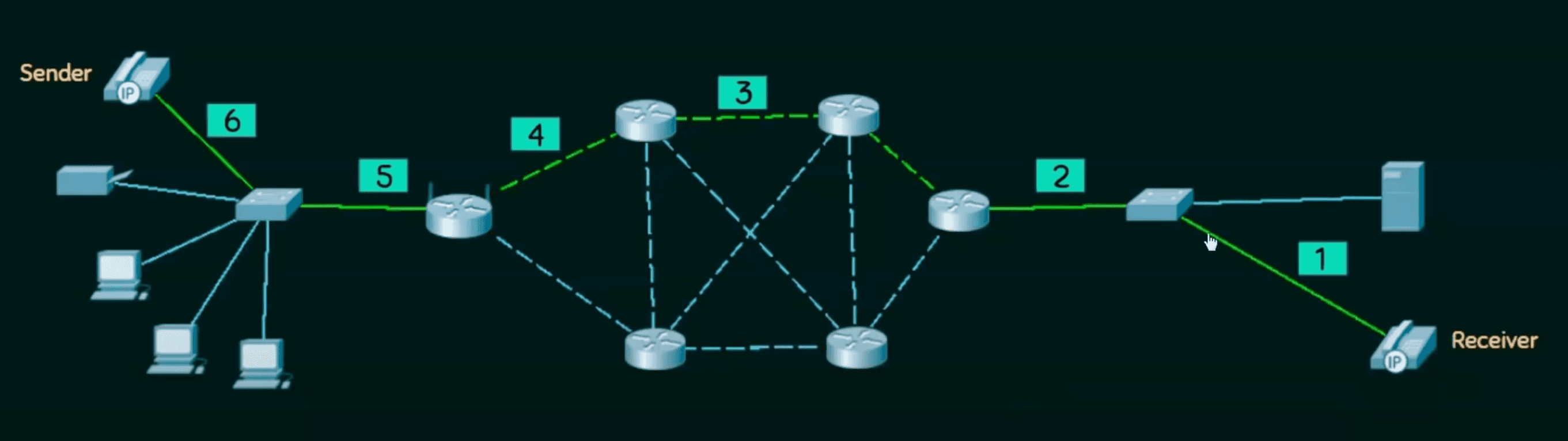
  • Then which is then forwarded using intermediary nodes (routers) which modify only the last three layers. Network, Data Link, and Physical
  • Finally data is de-encapsulated to extract the data.

7 Layers of OSI Model

Physical Layer:

  • Deals with physical connection.
  • Transmission of raw binary data (0's and 1's) over physical media (fiber optics, etc).
  • Eg: Ethernet Cable, USB, Bluetooth.
  1. Representation of bits: bits are encoded into signals - electric or optical.
  2. Data rate: transmission rate.

asdf

  1. Line configuration: Point-to-point or Multipoint.
  2. Physical topology.
  3. Transmission mode: (duplex)

Data Link Layer:

  • Ensures error-free data transfer between two devices on same network
  • Divides data into frames
  • Eg: MAC Addresses, Wi-Fi
  1. Framing.
  2. Physical address. (MAC)
  3. Access control. (authorization)
  4. Flow control. (data absorbed by receiver vs data send)
  5. Error handling. (resend)

Network Layer:

  • Handles routing and addressing of data across different networks
  • Divides data into packets, assigns IP address, chooses best path
  • Eg: IPv4, routers
  1. Logical addressing. (IP)
  2. Routing

Transport Layer:

  • Ensures reliable data delivery between devices
  • Divides data into segments, provides error recovery, flow control and retransmission of lost packets.
  • Eg: TCP, UDP
  1. Service-point addressing. (port addressing)
  2. Segmentation and reassembly.
  3. Connection control.
  4. Flow control.
  5. Error control.

Session Layer:

  • Manages and maintains connections (sessions) between devices
  • Establishes, maintains and terminates sessions. Synchronous + dialog control
  • Eg: APIs, NetBIOS
  1. Dialog control. (duplex)
  2. Synchronization. (adding checkpoints to process)

Presentation Layer:

  • Translates data into a format application layer can understand
  • Data encryption, compression and formatting. (from ACSII to Unicode)
  • Eg: SSL/TLS, JPEG, MP3
  1. Translation
  2. Encryption
  3. Compression.

Application Layer:

  • Provides services directly to the end user
  • Facilitates transfer related services like transfer, email and browsing.
  • Acts as interface b/w user application and network
  • Eg: HTTP, FTP, SMTP, DNS.
  1. Network virtual terminal.
  2. File transfer, access and management.
  3. Mail services.
  4. Directory services.

TCP/IP Model

  • Transmission Control Protocol / Internet Protocol
  • Backbone of internet.
  • Practical model focusing on simplicity and speed.
  • Tightly tied to protocols like TCP, IP, UDP.

Screenshot 2024-11-22 at 4.21.19 PM.png

4 Layers of TCP/IP Model

Application: Represents data to user, with encoding and dialog control.

Transport: Supports communication between different devices across different networks.

Internet: Determines the best path thought the network, assigns IP, etc

Network Access: Controls the hardware devices and media that make up the network.

Protocol Data Unit (PDU)

Named according to protocols of TCP / IP suite.

Screenshot 2024-11-22 at 4.32.10 PM.png


Transmission Media

Anything that can carry information from source to destination.

Guided Media : Wired

Twisted pair cable: consists of two conductors (copper) with plastic insulation. Telephone line. Coaxial cable: central core conductor of solid wire enclosed in insulation sheath. Cable TV. Fibre optical:

  • Made of glass or plastic.
  • Transmit signal in the form of light.
  • Using principles of total internal reflection.
  • Up to 1600 Gbps: higher bandwidth, less signal attenuation, no noise problem, no corrosion, light weight, greater immunity to tapping
  • Installation and maintenance, unidirectional light propagation, cost

Unguided Media: Wireless

Ground propagation

  • Waves travel through lower portion of atmosphere.
  • Omnidirectional.
  • Low frequency and large wave length.
  • Short range, depends on power.

Sky propagation

  • High frequency radio waves
  • Reflection between earth and ionosphere.
  • Greater distance with lower output.
  • Range up to 5000 kms

Line of sight propagation

  • Very high frequency signals transmitted from antenna to antenna.

Waves

γ\gamma rays -> X rays -> UV -> visible -> IR -> Microwaves -> FM -> AM -> Long wave lengths

  • Radio waves: omnidirectional. interference problems. can penetrate walls. government.
  • Microwaves: unidirectional, can be focused narrowly, cannot penetrate wall ,wide band so high data rates are possible, managed by government.
  • Infrared: short range communication. home appliances.

Switching

  • Switching in Computer Networks helps in deciding the best route for data transmission if there are multiple in a larger network.
  • One to one connection

Circuit Switching

  • Before data transmission, connection will be established.
  • Eg: Telephone Network. (time division multiplexing vs frequency division multiplexing)

Screenshot 2024-11-21 at 1.37.38 PM.png

  1. Connection
  2. Data Transmission
  3. Disconnection

Message Switching

Screenshot 2024-11-21 at 1.42.49 PM.png

  • First message is broken into individual pieces, which are then reassembled at the Intermediary node.
  • Then message is transferred as a complete unit and forwarded using Store and Forward mechanism.
  • Not suited for streaming media and real time applications.

Packet Switching

  • Internet is a packet switching network.
  • Message is broken into chunks called packets.
  • Each packet is send individually.
  • Each packet will have source and destination IP address with sequence number.
  • Sequence Number will help the receiver to
    • Sort the packets
    • Detect missing packets
    • Send acknowledgements

1. Datagram Approach - Packet Switching

Screenshot 2024-11-21 at 1.51.24 PM.png

  • Connectionless switching
  • Each independent entity is called as datagram.
  • Path is not fixed
  • Intermediary nodes take routing decision to forward the packets using their destination information.

2. Virtual Circuit Approach - Packet Switching

Screenshot 2024-11-21 at 1.54.15 PM.png

  • Connection Oriented Switching
  • A preplanned route is established before sending the message
  • Call request and call accept packets are used to establish the connection b/w sender and receiver
  • Path is fixed for the duration of a logical connection

Packet Switching Technology

Packet switching is the backbone of the Internet, dividing data into small pieces (packets) for efficient transfer:

  1. Data Splitting:
    • When you send a file or request, it is divided into smaller packets (e.g., a video is split into chunks).
    • Each packet contains a header (source and destination info) and payload (the data).
  2. Routing:
    • Packets travel independently through various routes across the Internet.
    • Routers decide the best path for each packet based on availability and speed.
  3. Reassembly:
    • At the destination, packets are reassembled into the original file, even if they arrive out of order.
  4. Error Checking:
    • If any packets are lost or corrupted during transmission, the receiving device requests a retransmission.

Advantages of Packet Switching

  1. Efficiency: Maximizes network bandwidth as packets use available routes.
  2. Fault Tolerance: If one route fails, packets can take alternative paths.
  3. Scalability: Handles large amounts of traffic without crashing.

ISDN (Integrated Services Digital Network)

Screenshot 2025-02-26 at 3.56.47 PM.png

  • Set of protocols for establishing and breaking circuit-switched connections, and for advanced call features for the users.
  • Developed around 1980-1990's.
  • Digital signals for transmission.
  • B-channel for data and D-channel for control and signaling.
  • BRI (basic rate interface) and PRI (primary rate interface).
  • Used to widely use it but declined due to low speed.

UNIT 2 : DATALINK LAYER

Data-link layer is divided into two sublayers.

  1. Logical Link Control (LLC) (TOP).
  • Flow control
  • Error control
  1. Media Access Control (MAC) (Bottom).
  • Specific access method for each LAN
  • Ethernet
  • Addressing at the level (Lan technology)

Framing is handled by both.

Media Access Control

When multiple nodes or stations are connected and use a common link, we need a multiple-access protocol to coordinate access to link.

Screenshot 2025-02-26 at 4.22.25 PM.png

Propagation Delay Time taken by bit for travel from point A to point B in transmission media.

Tp=DistancePropagation SpeedT_p = \frac{\text{Distance}}{\text{Propagation Speed}}

Screenshot 2025-02-26 at 4.55.17 PM.png

Transmission Delay ( TTT_T or TfrT_{fr} ) Time taken by sender to send all bits in packets. If first bit is put on line at time t1t_1 and last bit on t2t_2 , then TT=t2t1T_T = t_2 - t_1

TT=Packet Length (L)TransmissionrateorBandwidth(B)T_T = \frac{\text{Packet Length (L)}}{Transmission rate or Bandwidth (B)}

Random Access

  • No station is superior to another station and none is assigned control over another.
  • Transmission is random and stations compete to access the medium.
  • If more than one station tries to send data, there is an access conflict collision and the frame is lost.

All the protocols in Random access approach will answer the following questions

  1. When can the station access the medium?
  2. What can the station do if the medium is busy?
  3. How can the station determine the success or failure of the transmission?
  4. What can the station do if there is an access conflict?

Aloha

LAN based protocol where each stations sends a frame whenever it has a frame to send.

Simple but prone to collision.

Two Types : Pure Aloha and Slotted Aloha.

Screenshot 2025-02-26 at 9.06.30 PM.png

Vulnerable Time: During which there is a possibility of collision, if another frame is send.

Pure ALOHA Vulnerabe time=2×Tfr\text{Pure ALOHA Vulnerabe time} = 2 \times T_{fr}

i.e. No station should send any frame one TfrT_{fr} before or one TfrT_{fr} after, the start of transmission of current frame.

G - average no. of frames generated by system during one frame transmission. S - average no. of successfully transmitted frames

Throughput for pure ALOHA is S=G×e2G\text{Throughput for pure ALOHA is } S = G \times e^{-2G} Smax=0.184 for G=12S_{max} = 0.184 \text{ for } G = \frac{1}{2}

Slotted Aloha

To improve efficiency of pure aloha, we send frames only in slots of TfrT_{fr} time.

Now vulnerable time is reduces to half of pure. i.e. TfrT_{fr} Hence, efficiency doubled 37%.

Synchronous.

Screenshot 2025-02-27 at 12.46.19 PM.png


Carrier Sense Multiple Access (CSMA)

Each station senses medium before sending frame to reduce collisions.

The possibility of collision still exists due to propagation delay. Frames take time to send to each station, hence station may find the medium idle to collision with the incoming frame.

Hence, the vulnerable time is TpT_p

Screenshot 2025-02-27 at 11.47.18 AM.png

Persistence Method

What should station do if channel is busy/idle

1-persistence method: continuously sense station and send as soon as it becomes idle. Simple but high changes of collision if multiple stations are detecting simultaneously.

Non-persistence method: Senses station at random intervals, and sends if idle. Reduces change of collision significantly.

P-persistence method: Continuously senses if station is idle and starts generating probability pp at time slots to send frame per station if it's probability if more than pp .

Screenshot 2025-02-27 at 11.46.24 AM.png


CSMA with collision Detection (CSMA/CD)

In the worst case scenario, it will take station twice of propagation delay to detect if there was a collision. That's why we send the frame of that size to detect and reduce collisions.

TT=2×TpT_T = 2 \times T_p

Energy level is zero for idle; normal for transmission; and abnormal for collision (double normal).

Screenshot 2025-02-27 at 12.09.57 PM.png


CSMA with Collision Avoidance (CSMA / CA)

Hard to detect collisions using energy in wireless medium (lost in transmission). That's why we try to avoid using these strategies.

Interframe Space (IFS) Collisions are avoided by deferring transmission even if channel is idle by a periodic time called IFS. Can prioritize using variable.

Contention Window The contention window is an amount of time divided into slots. A station that is ready to send chooses a random number of slots as its wait time. Which doubles with time.

If the station finds the channel busy, it does not restart the process; it just stops the timer and restarts it when the channel is sensed as idle. This gives priority to the station with the longest waiting time.

Screenshot 2025-02-27 at 12.27.39 PM.png

Acknowledgement Use positive acknowledgements and time-out timer to guarantee receiver receives the frame.

Screenshot 2025-02-27 at 12.45.17 PM.png


Flow and Error Control

Receiver keeps a temporary buffer until incoming data is processed.

  • Slower than transmission rate.
  • Sends acknowledgement if buffer is almost full, for smooth data flow.

In DLL, Error control is commonly implemented through the Automatic Repeat Request (ARQ) process, where detected errors trigger the retransmission of specific frames to maintain data integrity.

Sliding Window Protocol

  1. Stop-and-wait ARQ
  2. Go-back-N ARQ
  3. Selective Repeat ARQ

Stop-and-Wait ARQ

  • Each frame is send one by one, only after sender receives acknowledgement.
  • If data is lost or corrupted and acknowledgement isn't received, sender resends frames after a time-out.
Screenshot 2025-02-27 at 1.05.32 PM.png
  • Use sequence numbers (which alternate b/w 0 and 1) to sort frames and avoid duplicates.
  • Acknowledgements ask for next frame if received properly for a more useful communication.

Queuing Delay DelayquDelay_{qu} = Time packet waits in input and output queues in a router.

Processing Delay DelayprDelay_{pr} = Time required to process a packet at destination host.

Performance for Stop and Wait

Total Time=Tt(data)+Tp(data)+Delayque+Delaypr+Tt(ack)+Tp(ack)+Delayque+Delaypr\text{Total Time} = T_{t(data)} + T_{p(data)} + Delay_{que} + Delay_{pr} + T_{t(ack)} + T_{p(ack)} + Delay_{que} + Delay_{pr}
  • Delays are generally zero for numerical, along with Tt(ack)T_{t(ack)} , since small size.
  • Also propagation delay is almost same for both.
Total Time=Tt(data)+2×Tp\text{Total Time} = T_{t(data)} + 2 \times T_p

Sometimes 2×Tp2 \times T_p is also called Round Trip Time (RTT).

Efficiency ( η\eta ) Efficiency is useful time divided by total cycle time.

η=TtTt+2×Tp\eta = \frac{T_t}{T_t + 2 \times T_p} η=11+2×α (where α=TpTt)\eta = \frac{1}{1 + 2 \times \alpha} \text{ (where } \alpha = \frac{T_p}{T_t})

Effective Bandwidth / Throughput

Throughput=η×B (efficiency * bandwidth)\text{Throughput} = \eta \times B \text{ (efficiency * bandwidth)}

Go-back-N ARQ

Send multiple frames before receiving acknowledgements using sliding window concept, for channels with high bandwidth to improve efficiency.

Send window covers sequence number of frames that can be transit, max value =2m1= 2^m - 1

Screenshot 2025-02-27 at 1.44.55 PM.png

Timer We only use one timer for each window, and send outstanding packets at time-out.

Acknowledgement Receiver sends positive acknowledgement for frames that arrive in correct order and silent for lost ones.

Screenshot 2025-02-27 at 1.47.17 PM.png

We gradually slide window as we receive acknowledgements.

Efficiency Since WsW_s (window size) packets are send together, our efficiency improves.

η=Wb1+2×α\eta = \frac{W_b}{1 + 2 \times \alpha}
  • For maximum efficiency, Wb=1+2×αW_b = 1 + 2 \times \alpha
  • Number of bits required for sequence number =ceil(log2(1+2)α)= ceil(\log_2{(1 + 2)} \alpha)

Problem If one packet is lost during transmission, all packets ahead in the window are resend, which is very inefficient.

Selective Repeat ARQ

If the connection is not stable, the Selective Repeat ARQ is better as it only resends the frames that didn't arrive correctly, saving time and data.

Receiver stores frames in wrong order until they can be arranged properly. Hence, require equal room for sending and receiving frames to work more efficiently. i.e. 2m12^{m - 1}

Screenshot 2025-02-27 at 1.58.45 PM.png

Each frame has its own countdown timer and sends negative acknowledgements if lost.

Safer but less performant.

Piggybacking

We can send frame with receivers acknowledgement to able bidirectional protocol efficiency.

Both ends need separate timers and buffers. Complicated but effective.


Types of Errors

Data transmitted between nodes can sometimes be corrupted during transmission.

Single-bit error Scenario where only one bit in a data unit (byte or packet) is changed. Less common.

Burst error Range of bits from first alteration to last within a data unit. More common due to data rate and noise.

Hamming distance

d(x, y) is the count of dissimilar bits in both data of same size.

Simple Parity-check Code

We maintain a parity bit to keep bit count even and verify at receivers end. Otherwise there has been an error.

Screenshot 2025-02-27 at 4.01.10 PM.png

2D parity check to identify as well as correct a single bit error.

Hamming Codes

Error detecting codes designed to detect up to two errors or correct one single error.

Relationship between nn and kk in hamming code is k=2rr1k = 2^r - r - 1 .

Screenshot 2025-02-27 at 4.34.14 PM.png

  • Eg: for bits n = 7 and k = 4.
  • For r=3r = 3 ; k=2331=4k = 2^3 - 3 - 1 = 4
  • Parity bits =20,21,2r1=1,2,4= 2^0, 2^1, \ldots 2^{r - 1} = 1, 2, 4
    • P1P_1 bit takes one and leaves one. i.e. 1,3,5,7
    • P2P_2 bit takes one and leaves one. i.e. 2,3,6,7
    • P3P_3 bit takes one and leaves one. i.e. 4,5,6,7

We can place data bits at 3, 5, 6, 7. And maintain all three parities. If any bits changes, check parity from 3 to 1. And write down 1 and 0 based on error. The forming binary number in the error bit.

Checksum

While sending numbers across the internet, we send it's negative sum with it, and check if sum at receivers end is zero.

We wrap extra bits in sum and take its 1's complement, while sending. And do the same at receivers end.

Screenshot 2025-02-27 at 4.50.29 PM.png

Cyclic Redundancy check

  • We can create cyclic codes to correct errors.
  • In the encoder, the dataword has k bits; the codeword has n bits.
  • Size of the dataword is augmented by adding nkn - k 0s to the right-hand side of the word.
  • nn -bit result is fed into the generator.
  • Generator uses a divisor of size nk+1n - k + 1 , predefined and agreed upon.
  • Generator divides the augmented dataword by the divisor.
  • Quotient of the division is discarded; the remainder is appended to the dataword to create the codeword.
Screenshot 2025-02-27 at 5.15.03 PM.png

Encoder

Screenshot 2025-02-27 at 5.15.21 PM.png

Decoder

Screenshot 2025-02-27 at 5.15.34 PM.png

Polynomial We can represent a binary no. in terms of polynomial and perform the same cyclic redundancy check.

Index codeword from 0 to n1n - 1 , which work as powers and 0/1's are co-efficients.


Ethernet

  • Technology for connecting devices in wired LAN or MAN.
  • First standardized as IEEE 802.3 in 1983.
  • Initially coaxial cable, now twisted and even optical fiber cables.
  • From 2Mbps to 100Gbps.
  • Offers several wiring and signaling options.
  • 1500 Max transfer unit.
  • Data is segmented into frames with source and dest address with error handling.
  • Wi-Fi, a wireless protocol standardized as IEEE 802.11, alternate to ethernet in LAN.
  • Operators uses bus topology.
  • No acknowledgement by default.

Standard Ethernet

  • Connectionless and unreliable.
  • Frames are sent independently.
  • No acknowledgement are sent if data is corrupted or lost.
  • Simple and easy to install and reconfigure.
  • Not suitable for real time application, possibility of collisions.
  • No idea of priority.

Screenshot 2025-02-27 at 6.03.43 PM.png

  • Preamble: Alerts the station that frame is going to start. Establish bit synchronization.
  • Start Frame Delimiter (SFD): 10101011, marks beginning of frame.
  • Destination and Source Addresses: MAC address of source and destination.
  • Length: To define variable sized frame.
  • Data: Variable size (46 bytes to 1500 bytes) as payload. Either add 0's or fragment data if out of range. Minimize limit to avoid vulnerable time and max limit to prevent monopoly of shared medium.
  • CRC: Cycle redundancy check for error detection.

Token Bus

  • IEEE 802.4
  • Designed to work over a bus topology but shares the token-passing access method for controlling the network traffic.
  • No collisions.
  • Provides predictable network timing compared to ethernet, useful for real time apps.
  • Up to 10Mbps.

Token Ring

  • IEEE 802.5
  • Operates over a star or ring topology, where data packets are circulated in one direction from one device to the next until they reach their destination.
  • No collisions.
  • From 4Mbps to 100Mbps.
  • Still replaced by ethernet due to speed and simplicity.

Fiber Distributed Data Interface (FDDI)

  • Standard for data transmission in LAN.
  • Optical fibers, also copper (CDDI).
  • Range up to 200 kilometers.
  • Dual ring architecture.
  • Token passing. No collision. Real time and predictable.
  • High speed. up to 100Mbps in 1980's.
  • No scalable, expensive.
  • Also replaced by ethernet.

Manchester Encoding

At the sender, data are converted to a digital signal using the Manchester scheme; at the receiver, the received signal is interpreted as Manchester and decoded into data.

The duration of the bit is divided into two halves. The voltage remains at one level during the first half and moves to the other level in the second half. The transition at the middle of the bit provides synchronization.

Screenshot 2025-02-28 at 12.54.50 AM.png

By G.E. Thomas: Go up at 0 and down at 1. By IEEE: Go down at 0 and up at 1.


UNIT 3 : NETWORK LAYER

  • Source to Destination delivery of packets across multiple networks.
  • Uses Logical addressing to identify sender and receiver.
  • Finds best Route to send packets using routing protocols.
  • Packetize payload by adding essential headers.
  • Checks for error and flow control.
  • Manages network congestion.

IPv4

Operates as an unreliable connectionless datagram protocol, offering a best-effort delivery service which doesn't guarantee packet safety or order.

  • IPv4 treats each datagram independently.
  • IPv4 packets might experience corruption, loss or delay causing network congestion.
  • Coupled with reliable protocol like TCP, forming TCP/IP protocol stack for secure data delivery.

Screenshot 2025-02-28 at 1.39.54 AM.png

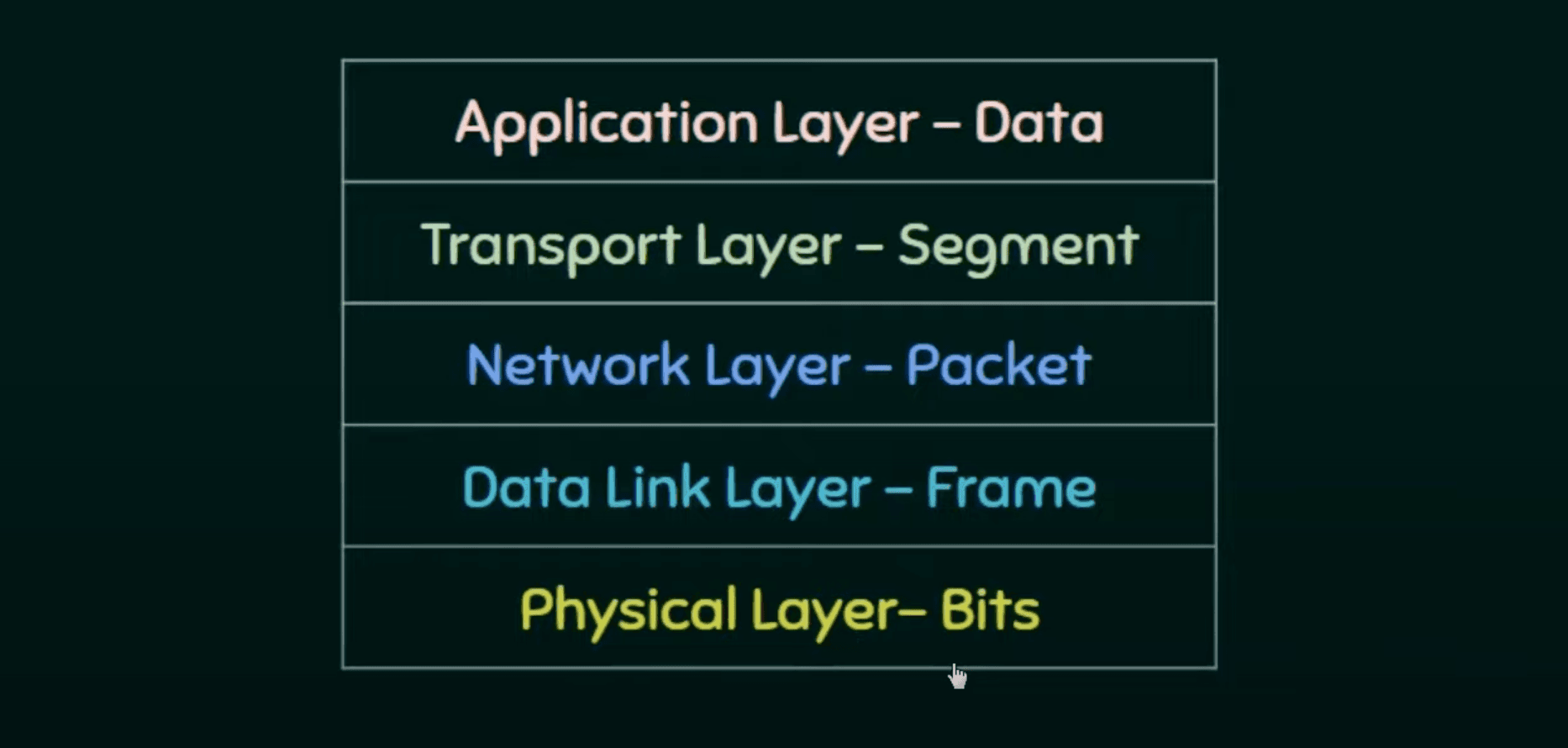
Packets used by IP is called a Datagram. Of variable length consisting of two parts: header and payload (data). Headers (20 to 60 bytes) contains essential information for routing and delivery.

Version Number (VER) (4 bits) Defines version of IP protocol. (0100 or 0110)

Header Length (HLEN) (4 bits) Total length of datagram header (in bytes) scaled down by 4 factor.

  • Minimum length of IP header = HLEN = 0100 -> 4 x 4 -> 20 bytes
  • Maximum length of IP header = HLEN = 1111 -> 15 x 4 -> 60 bytes

Service type (8 bits) First 3 bits represent precedence/priority. 000 to 111.

Next 4 bits are called TOC bits:

  • D: Minimize delay
  • T: Maximize throughput
  • R: Maximize reliability
  • C: Minimize cost
0000 - Default
0001 - Sasta - NNTP
0010 - Pakka - SNMP
0100 - Bohot sara - FTP (data)
1000 - Jaldi - FTP (control)

Total Length (16 bits) Total length of IP datagram in bytes.

  • Minimum total length = 20 bytes of header + 0 bytes of data = 20 bytes
  • Maximum total length = max value by 16 bits = 65535 bytes.
Length of Data=Total length(HLEN)×4\text{Length of Data} = \text{Total length} - (HLEN) \times 4

Identification (16 bits) Identifies datagram originating from a source host (even after fragmentation) and helps reassemble at destination.

Fragmentation Process of dividing datagram into fragments during transmission.

  • offset (13 bits) shows relative position of fragment w.r.t whole datagram.
  • Since size that be huge, we store index scaled down by a factor of 8.

Screenshot 2025-02-28 at 2.24.57 AM.png

Flag field (3 bits)

  1. Bit is reserved (not used)
  2. D-bit (Do-not fragment bit): tells not to fragment this datagram, if set (1).
  3. M-bit (More fragment bit): tells this is not the last fragment, if set.

Time-to-live (TTL) (8 bits)

  • Dictates remaining number of hops (via router) left.
  • Each routes keeps decrementing this value.
  • And datagram is discarded if TTL hits zero.
  • Preventing datagram from circulating infinitely.
  • And to restrict it's journey.

Protocol (8 bits) When the datagram arrives at destination, this value helps to define which protocol the payload should be delivered to (at transport layer). Eg: UDP or TCP.

Header Checksum (16 bits) This field only verifies the header (not the payload) at every router. Datagram is discarded if not verifies, otherwise is altered to accommodate changes in header.

Variable Part (Options + Padding) (0 to 40 bytes)

  • End of Option - 1 byte - padding at end.
  • Record route - to trace datagram's path - up to 9 router addresses.
  • Strict Source route - Define path, otherwise discard.
  • Loose source route - Must visit defined routers, but can visit others as well.
  • Timestamp - Record time of datagram processing by route. For research.

IPv6

IPv6 is the next-generation Internet Protocol designed to address limitations of IPv4, particularly in address space and header efficiency. It still operates as an unreliable connectionless datagram protocol with best-effort delivery, but with significant improvements.

Each packet is made up of:

  • Base Header
  • Payload
    • Upper layer data
    • Extension Header (optional)

Screenshot 2025-02-28 at 9.21.14 PM.png

Header Format:

  • Fixed header size of 40 bytes — simpler than IPv4's variable header (20–60 bytes).
  • Version (4 bits): Always set to 6.
  • Traffic Class (8 bits): Similar to IPv4's service type.
  • Flow Label (20 bits): To identify and manage packet flows for Quality of Service (QoS).
  • Payload Length (16 bits): Specifies the length of the data following the header.
  • Next Header (8 bits): Identifies the type of the next header (could be a transport layer protocol like TCP/UDP or an extension header).
  • Hop Limit (8 bits): Replaces IPv4's TTL.
  • Source & Destination Addresses (128 bits each): Ensure precise routing across a vast network.

No fragmentation by routers: Unlike IPv4, routers do not fragment IPv6 packets. Instead, sending host performs Path MTU Discovery to determine the appropriate packet size.

Extension Headers:

  • Allow additional functionalities (e.g., routing, security, fragmentation) without bloating the fixed header.
  • Placed between the fixed header and the upper-layer protocol header, providing a flexible mechanism to extend IPv6 capabilities.

IPv4 vs IPv6 Comparison

FeatureIPv4IPv6
Address Size32 bits (4 bytes)128 bits (16 bytes)
Address FormatDotted-decimal (e.g., 192.168.1.1)Colon-separated hexadecimal (e.g., 2001:0db8::1)
Header Length20–60 bytes (variable)40 bytes (fixed)
FragmentationPerformed by both routers and senderHandled only by the sender (routers do not fragment)
Header ChecksumPresent (verifies header integrity)Removed (reduces processing overhead)
Options/ExtensionsOptions field (limited and variable)Extension headers (modular and flexible)
Quality of ServiceType of Service fieldTraffic Class and Flow Label for improved flow management
SecurityIPsec is optionalDesigned with native support for IPsec
NAT RequirementOften required due to limited address spaceAbundant address space eliminates the need for NAT

Advantages of IPv6

  • Expanded Address Space: Provides a virtually limitless number of IP addresses.
  • Simplified Header Format: Fixed header size improves processing speed and efficiency.
  • Improved Routing: Hierarchical addressing and simplified header structure allow for more efficient routing.
  • Enhanced QoS: Traffic Class and Flow Label fields facilitate better Quality of Service management.
  • Native Security: Designed with mandatory IPsec support for robust network security.
  • Auto-Configuration: Supports plug-and-play capabilities, making network configuration easier.
  • Eliminates NAT: Abundant addresses remove the need for Network Address Translation (NAT), simplifying end-to-end connectivity.

Need of additional protocols

  • Need physical address (MAC).
  • Need local network IP address.
  • Need better error and flow control.
  • Need protocol for multicast delivery.

Address Resolution Protocol (ARP)

  • IP address of next node alone isn't enough for transmission, need link-layer address (MAC).
  • To remedy that, sender included it's MAC and IP address of both sender and receiver and broadcasts it to the local network.
  • The receiver identifies himself, and sends his MAC address to sender's IP as response.
  • Finally packet is unicast directly to the receiver.

Reverse ARP (RARP)

  • When a device is connecting to internet for the first time. It knows it's MAC address but not IP address.
  • A RARP request is broadcasted on local network with its physical address.
  • The RARP server checks list and sends its logical address as response.

Internet Control Message Protocol (ICMP)

Designed to provide error-reporting and control mechanism. ICMP messages are divided into two broad categories.

1. Error Reporting

ICMP doesn't correct errors, only reports them.

  • Time exceeded message: Sent to source IP from discard packet if time to live expires.
  • Parameter problem: Sent when header gets corrupted and checksum invalidates.
  • Destination unreachable: Sent when packet failed to reach destination.
  • Redirection: Sent to inform source to update its routing information.

No ICMP error message if ICMP messages or fragments or multicast or special addresses.

2. Query

ICMP can diagnose some network problems.

  • Echo request and reply: Essential diagnostic tools enabling network managers and users to pinpoint network issues and confirm that IP protocols in sender and receiver systems are in sync.
  • Router Solicitation and Advertisement: A router periodically broadcasts this message to inform hosts about its existence.
  • Address-Mask Request and Reply: The router receiving the address-mask-request message responds with an address-mask-reply message, providing the necessary mask for the host.
  • Timestamp Request and Reply: to synchronize clocks on two machines.

Internet Group Message Protocol (IGMP)

Enables one-to-many communication.


IP Addresses

  • IPv4 are 32bits in length. Giving 2322^{32} addresses. Over 4 billion possible devices. smol.
  • IPv6 is 128 bits in length. Which is over 3.4×10383.4 \times 10^{38} devices. Too big.
  • IP address is unique and universal.
  • Every node in computer network is identified with help of IP address.
  • Logical Address, since can change based on location of device.
  • Represented in decimal and has 4 octets (x.x.x.x)
  • 0.0.0.0 to 255.255.255.255 (32bits)
  • Decimal dotted notation and binary notation.
Now how many devices can you host on the same network?
  • You might think, since network portions remains the same. And its from 0-255. 256?
  • WRONG!
  • 192.168.1.0 is reserved for the first born Network Address.
  • 192.168.1.255 is reserved for the chatty Broadcast Address. He everything to everyone.

So that's makes it a total of 254 different hosts!

Classes of IPv4 Address (Classful)

IP address classes categorize IPv4 addresses based on their default network size and first octet.

Key Features

  • Class A: Large networks.
    • Binary: First bit is 0.
    • Range: 0.0.0.0 – 127.255.255.255.
    • Default Mask: 255.0.0.0.
  • Class B: Medium-sized networks.
    • Binary: First two bits are 10.
    • Range: 128.0.0.0 – 191.255.255.255.
    • Default Mask: 255.255.0.0.
  • Class C: Small networks.
    • Binary: First three bits are 110.
    • Range: 192.0.0.0 – 223.255.255.255.
    • Default Mask: 255.255.255.0.
  • Class D: Multicasting.
    • Binary: First four bits are 1110.
    • Range: 224.0.0.0 – 239.255.255.255.
  • Class E: Experimental.
    • Binary: First four bits are 1111.
    • Range: 240.0.0.0 – 255.255.255.255.

Screenshot 2024-11-22 at 5.06.44 PM.png

Hence, to find out a class of an IP address. Simply convert first octet of Dotted-decimal notation into binary, and count no. of 1's in the beginning.

Masks in IPv4 Addressing (Subnet Mask)

A mask in IPv4 addressing, also known as a subnet mask, is used to divide an IP address into two parts:

  1. Network Portion: Identifies the network.
  2. Host Portion: Identifies individual devices within that network.

The subnet mask determines which part of the IP address belongs to the network and which part belongs to the host.

Default Masks for IPv4 Classes (Subnet classes)

Subnet classes divide an IP address space into smaller subnets using subnet masks.

  • Subnet masks define the network and host portions of an IP address.
    • Example: 255.255.255.0 → Network (first 24 bits) and Host (last 8 bits).
  • Custom subnet masks allow more flexibility:
    • Example: 255.255.240.0 (binary: 11111111.11111111.11110000.00000000).

Class A

  • Binary Notation: 11111111.00000000.00000000.00000000
  • Dotted-Decimal Notation: 255.0.0.0
  • Network Portion: First 8 bits (1st octet).
  • Host Portion: Last 24 bits (remaining 3 octets).
  • IP Range: 0.0.0.0 to 127.255.255.255.

Class B

  • Binary Notation: 11111111.11111111.00000000.00000000
  • Dotted-Decimal Notation: 255.255.0.0
  • Network Portion: First 16 bits (1st and 2nd octets).
  • Host Portion: Last 16 bits (3rd and 4th octets).
  • IP Range: 128.0.0.0 to 191.255.255.255.

Class C

  • Binary Notation: 11111111.11111111.11111111.00000000
  • Dotted-Decimal Notation: 255.255.255.0
  • Network Portion: First 24 bits (1st, 2nd, and 3rd octets).
  • Host Portion: Last 8 bits (4th octet).
  • IP Range: 192.0.0.0 to 223.255.255.255.

IP Address Classes define broad categories of IP ranges (A, B, C, etc.).

  • Subnet Classes are subdivisions within those ranges using subnet masks.
  • The subnet mask is essential for routing and defining subnets within larger networks.
  • Modern networking uses CIDR for flexible and efficient IP allocation.

Classless Inter-Domain Routing (CIDR)

Given the address 205.16.37.39/28, let’s calculate the following:

(i) First Address of the Block (Network Address)

  1. CIDR Notation: /28 means the subnet mask has 28 bits set to 1, and the remaining 4 bits are 0. The subnet mask in dotted decimal is 255.255.255.240.

  2. Network Address: The first address is obtained by setting the host bits (the last 4 bits) to 0.

  • Convert 205.16.37.39 to binary:
205:   11001101
16:    00010000
37:    00100101
39:    00100111
  • Retain only the network bits (first 28 bits) and set the last 4 bits to 0:
11001101.00010000.00100101.00100000 (binary) = 205.16.37.32
  • First address : 205.16.37.32

(ii) Last Address of the Block (BroadCast Address)

The last address is obtained by setting all the host bits (last 4 bits) to 1:

11001101.00010000.00100101.00101111 (binary) = 205.16.37.47
  • 205.16.37.47

(iii) Total Number of Addresses

  1. The number of addresses in a /28 block is calculated as  2(3228)=24=162^{(32 - 28)} = 2^4 = 16
  • Total Addresses: 16
  1. However, 2 addresses are reserved:
    • Network address: 205.16.37.32.
    • Broadcast address: 205.16.37.47.
  • Usable Addresses for Hosts:  16 - 2 = 14 .

Broadcast

  • limited : private
  • Direct: another network

Routing

  • Routing is the process of selecting paths in a network along which to send network traffic.

  • While taking a packet and sending it to a path is actually switching.

  • Routers are the devices that perform this function by maintaining and updating routing tables, which list the routes to various network destinations.

  • Routing table contains network information and helps determine the best interface to send incoming packets to reach their destination.

  • Static Table has manual entries. knows all routers in the network. Not possible.

  • Dynamic Table is automatically updated without human intervention when there's a change in the internet, such as topology or traffic.

Flooding

  • Send packet to all possible routes and then we can be sure that at least one packet will reach the destination.
  • No routing algorithm required, shortest path guaranteed, highly reliable.
  • Duplicate packets will arrive at destination, High traffic.

Unicast Routing Protocols

Unicast means the transmission from a single sender to a single receiver. It is a point-to-point communication between the sender and receiver.

They share routing tables with one another. Eg: Distance Vector, Link-state, Path-Vector.

Intra-Domain Routing

  • Definition: Routing within a single administrative domain or autonomous system (AS).
  • Characteristics:
    • Focus on fast convergence and efficient use of resources within the domain.
    • Typically uses protocols designed for relatively smaller, controlled environments.
  • Examples: OSPF (Open Shortest Path First), RIP (Routing Information Protocol).

Inter-Domain Routing

  • Definition: Routing between different autonomous systems.
  • Characteristics:
    • Handles complex policy decisions and scalability issues across diverse administrative domains.
    • Emphasizes policy, security, and scalability over rapid convergence.
  • Examples: BGP (Border Gateway Protocol).

RIP treats all routes the same and cost of each hop is 1. While OSPF gives us the administration to assign cost for passing through a network and choose most optimal path.

Distance-Vector Routing

Screenshot 2025-05-19 at 4.51.00 PM.png
  • Basic Principle:
    • Each node maintains a vector (table) of minimum distance to every node.
    • TO | COST | NEXT
    • Each router periodically sends its routing table (TO | COST) to its directly connected neighbors.
    • Triggered Update A node sends its two-column routing table to its neighbors anytime there is a change in its routing table. (update or failure)
    • Routers update their tables based on the best information received from neighbors.
  • Key Features:
    • Simplicity: Relatively easy to implement with low overhead.
    • Periodic Updates: Information is exchanged at regular intervals, which can lead to slower convergence.
  • Common Issues:
    • Count-to-Infinity Problem: In the event of a route failure, routers might gradually increase the metric for a bad route before realizing it’s unreachable.
    • Routing Loops: Incorrect or outdated information can cause data packets to circulate indefinitely.

Two-Node Instability in Distance-Vector Routing

  • Definition: A condition in which two routers (or nodes) continuously update each other with routing information, leading to constant changes (oscillations) in their routing tables.
  • Cause:
    • Occurs when a change (like a link failure) in one router’s routing table is repeatedly propagated back and forth between two routers.
    • Without proper controls, each router may erroneously believe a better route exists through its neighbor, triggering further updates.
  • Impact:
    • Routing Loops and Oscillations: Leads to longer convergence times and unstable network performance.
  • Mitigation Techniques:
    • Implementing mechanisms such as split horizon and route poisoning to break the feedback loop.

Split Horizon

  • Concept:
    • A technique used in distance-vector routing to prevent routing loops.
  • How It Works:
    • A router does not advertise a route back out the interface from which it was learned.
    • This prevents two routers from repeatedly sending the same route back and forth (a common cause of the two-node instability).
  • Benefits:
    • Reduces the likelihood of routing loops.
    • Helps to speed up convergence by ensuring that erroneous information isn’t fed back into the routing process.
  • Additional Measures:
    • Often used in conjunction with route poisoning (marking a route as unreachable) to further improve stability.

Screenshot 2025-05-19 at 4.51.43 PM.png

  • Basic Principle:
    • Unlike distance-vector routing, each router using a link state protocol maintains a complete map of the network topology.
  • How It Works:
    • Routers periodically broadcast the state (status and cost) of their directly connected links to all other routers in the network.
    • Each router independently runs a shortest path algorithm (commonly Dijkstra’s algorithm) on this map to compute the best paths to all destinations.
  • Key Advantages:
    • Faster Convergence: Changes in the network are propagated quickly, reducing the window for routing loops or incorrect paths.
    • Robustness: A complete topology view makes it easier to compute alternate routes and avoid loops.
  • Examples:
    • OSPF (Open Shortest Path First)
    • IS-IS (Intermediate System to Intermediate System)
  • Trade-offs:
    • Resource Intensive: Requires more memory and CPU power to store the complete network map and perform frequent calculations.
Distance-Vector Routing (DVR)Link-State Routing (LSR)
In the distance-vector routing algorithm, each router tells its neighbors what it knows about the whole internet.In the link-state routing algorithm, each router tells the whole internet what it knows about its neighbours.
Based on the idea of Local KnowledgeBased on the idea of Global Knowledge
Bandwidth requirement is lessBandwidth requirement is high
Roughly based on the idea of Bellman‑Ford algorithmDirectly based on the idea of Dijkstra’s algorithm
Traffic is usually lessTraffic is usually high
Converges slowlyConverges faster
Counts to infinityNo count to infinity
RIPOSPF

UNIT 4 : TRANSPORT LAYER

Congestion

  • Definition: Occurs when offered load > network capacity, leading to queue buildup, delay, and packet loss.
  • Symptoms: High latency, jitter, dropped packets, throughput collapse.

When network demand exceeds capacity, packets queue up, causing delays and losses. Effective congestion control prevents or reacts to overload, ensuring smooth and fair data flow.

1. Open‑Loop (Preventive) Control

Goal: Shape traffic before it enters the network to limit bursts and smooth peaks.

  • Leaky Bucket
    • Mechanism: Packets enter a queue and exit at a constant rate. If the queue is full when a new packet arrives, it’s dropped.
    • Effect: Eliminates sudden spikes; enforces a strict, steady output rate.
    • Analogy: A bucket with a small hole—water drips out evenly regardless of how fast it’s poured in.
  • Token Bucket
    • Mechanism: Tokens accumulate at a set rate up to a maximum. Sending a packet consumes a token; if none are available, packets wait or are discarded.
    • Effect: Allows occasional bursts (up to stored tokens) while enforcing a long‑term average rate.
    • Analogy: Earning tokens in a jar—you can spend them in a burst but refill happens steadily.
  • Traffic Policing & Shaping
    • Policing: Drops or marks packets that exceed a rate limit.
    • Shaping: Buffers excess packets and releases them at the allowed rate to smooth traffic.
  • Random Early Detection (RED)
    • Mechanism: Monitors average queue length. When it crosses a lower threshold, randomly drops or marks incoming packets (increasing probability as the queue grows). Above a higher threshold, it drops all.
    • Effect: Signals congestion early, preventing sudden buffer overflows.
    • Analogy: A traffic cop who warns drivers before the road is jammed.
  • Queuing Disciplines
    • Priority Queuing: Higher‑priority flows go first, delaying lower‑priority traffic.
    • Fair Queuing: Splits capacity evenly among flows, ensuring no single flow dominates.

2. Closed‑Loop (Reactive) Control

Goal: Hosts adjust send rates based on feedback (losses, delays, or explicit marks) received from the network after it happens.

2.1 TCP’s AIMD Algorithm

  • Additive Increase: After each round‑trip time (RTT) with no congestion, increase congestion window (cwnd) by one Maximum Segment Size (MSS).
  • Multiplicative Decrease: On detecting packet loss, halve cwnd.

Balance: Gentle growth to find available bandwidth; quick back‑off on congestion.

2.2 TCP Phases

  1. Slow Start
    • cwnd starts small (e.g., 1 MSS).
    • Doubles each RTT until loss or a preset threshold (ssthresh).
  2. Congestion Avoidance
    • Switch to AIMD when cwnd ≥ ssthresh.
    • Linear growth: cwnd += 1 MSS per RTT, halve on loss.
  3. Fast Retransmit & Recovery
    • On three duplicate ACKs: immediately retransmit the missing segment without waiting for timeout.
    • Set cwnd to half of its value before loss (instead of full collapse), then resume AIMD from there.

Example:

  • Start: cwnd = 1 MSS
  • After 5 RTTs without loss: cwnd = 6 MSS
  • On loss: cwnd → 3 MSS, then growth resumes.

3. Summary

TechniqueBurst HandlingLong‑Term RateComplexity
Leaky BucketBlocks/drops excessFixed outputSimple
Token BucketAllows bursts up to BEnforces averageModerate
REDEarly, random dropsAdaptiveModerate
TCP AIMDAdapts to feedbackProbes capacityBuilt into TCP

Transport Layer Service

  • Network layer protocol only enables communication as computer-level (device-to-device).
  • Transport layer delivers message to appropriate process (PORT). Providing end to end communication.
  • Connectionless TL treats each segment as independent packet and delivers while Connection-oriented establishes connection before delivery.
  • Three common transport layer protocols.
    • UDP - connectionless and unreliable.
    • TCP and SCTP are connection oriented and reliable.

Addressing: Port Number

  • For communication, we must define local-host (Private IP), local-process, remote-host (Public IP), remote-process.
  • To define processes inside a host, we need secondary identifiers called port numbers. They are 16-bits integers ranging from 00 to 21612^{16} - 1 .
  • IANA (Internet Assigned Number Authority) has divided the port numbers into tree ranges.
    • Well-Known
      • 0 to 1023
      • Reserved for widely used services and protocols.
      • Eg: 80 (HTTP), 443 (HTTPS), 53 (DNS).
    • Registered
      • 1024 to 49151
      • Assigned to specific applications or services by organizations.
    • Dynamic/Private
      • 49152 to 65355
      • Used for temporary connections and can be used by any process.

The combination of an IP address and a port number is called Socket Address. Require pair of client and server socket address to communicate.


TCP

TCP is stream transfer protocol. It creates environment between two processes to share data. Providing flow control, error control and congestion control.

TCP Header

Segment consists of 20-60 byte header, followed by data from application program.

Pasted image 20250519173608.png

  • 16 bits for source and destination port address.
  • Sequence Number (32 bits)
    • To ensure connectivity, each byte is numbered in the range [0,2321][0, 2^{32} - 1] .
  • Acknowledgement Number (32 bits)
    • Next expected byte from the other side; valid only when the ACK flag is set.
  • HLEN
    • Header Length. Scaling factor = 4.
  • Reserved (6 bits)
    • Must be zero; reserved for future use.
  • Flags (6 bits)
    • URG (Urgent): urgent pointer field is significant
    • ACK (Acknowledgment): acknowledgment number is significant
    • PSH (Push): push function for data
    • RST (Reset): reset the connection
    • SYN (Synchronize): synchronize sequence numbers (connection setup)
    • FIN (Finish): no more data from sender, terminate connection
  • Window Size (16 bits)
    • Advertised receive window; flow control for how many bytes can be sent beyond the acknowledged sequence. (how much receiver can receive)
  • Checksum (16 bits)
    • Covers TCP header, payload, and a pseudo‑header from IP; ensures integrity.
  • Urgent Pointer (16 bits)
    • Offset (from sequence number) where urgent data ends; only valid if URG flag = 1.

TCP Connection

Pasted image 20250519181440.png

A TCP “three‑way handshake” establishes a reliable connection between a client and server before any data is exchanged. Here’s the step-by-step:

  1. SYN (Client → Server)
    • State transition: CLOSEDSYN‑SENT
    • Flags: SYN=1, all others = 0
    • Sequence Number: Seq = ISN_C (client’s chosen initial sequence)
    • Acknowledgment Number: not valid (usually 0)
    • Purpose: “Hey server, let’s open a connection; here’s my ISN.”
  2. SYN‑ACK (Server → Client)
    • State transition: LISTENSYN‑RECEIVED
    • Flags: SYN=1, ACK=1
    • Sequence Number: Seq = ISN_S (server’s chosen ISN)
    • Acknowledgment Number: Ack = ISN_C + 1 (confirms client’s SYN)
    • Purpose: “I agree to connect; here’s my ISN, and I’ve got your SYN.”
  3. ACK (Client → Server)
    • State transition: client moves from SYN‑SENTESTABLISHED; server moves from SYN‑RECEIVEDESTABLISHED
    • Flags: ACK=1 (only)
    • Sequence Number: Seq = ISN_C + 1 (next byte after client’s SYN)
    • Acknowledgment Number: Ack = ISN_S + 1 (confirms server’s SYN)
    • Purpose: “Connection confirmed—let’s start sending data.”

These three messages guarantee both endpoints have agreed on each other’s initial sequence numbers and are synchronized for reliable, in‑order data transfer. Now bi-directional data transfer takes place.


User Datagram Protocol (UDP)

  • Connectionless: No handshake; datagrams are sent independently.
  • Unreliable: No guarantees of delivery, ordering, or duplicate protection.
  • Lightweight: Minimal protocol overhead; suitable for low‑latency communications.
  • Stateless: Endpoints maintain no session state in the protocol itself.

UDP Header (8 bytes)

  • Source Port (16 bits): Optional; identifies sending application.
  • Destination Port (16 bits): Identifies receiving application.
  • Length (16 bits): UDP header + payload in bytes (min = 8).
  • Checksum (16 bits): Covers header, payload, and IP pseudo‑header; optional in IPv4 (mandatory in IPv6).

Typical Applications

  • Real‑time Media: VoIP, video conferencing (e.g., RTP over UDP).
  • Streaming: Live audio/video broadcasts where timeliness > completeness.
  • DNS: Quick query/response protocol for name resolution.
  • DHCP: Bootstrap IP configuration; uses broadcasts.
  • SNMP: Simple network management queries/traps.
  • Gaming: Fast updates in multiplayer games (state updates rather than guaranteed delivery).
  • Tunneling & VPNs: Encapsulation protocols (e.g., GRE, VXLAN).

Data Compression

  • Reduce Size: Minimize bits needed to represent data.
  • Compression Ratio:
ratio=original sizecompressed size\text{ratio} = \frac{\text{original size}}{\text{compressed size}}
  • Throughput & Latency: Trade‑off between speed of (de)compression and amount of reduction.

Types of Compression

  1. Lossless
    • Definition: Exact reconstruction of original data.
    • Use‑cases: Text, executables, archives, some images (e.g., PNG).
    • Run-length encoding, Huffman coding, Lempel Ziv Encoding.
    • Lower compression ratio.
  2. Lossy
    • Definition: Some information discarded; reconstruction is an approximation.
    • Use‑cases: Audio (MP3), images (JPEG), video (MPEG).
    • Higher compression ratio.

Run‑Length Encoding (RLE)

  • Idea: Replace repeated “runs” of the same symbol with a single count + symbol.
  • Good for: Data with long homogeneous runs (e.g. simple bitmaps, fax, icons).
  • Example: AAAAABBBCC5A3B2C.
  • Pros: Extremely simple, very fast.
  • Cons: Can inflate data with few repeats; not adaptive.

Huffman Coding

Screenshot 2025-05-19 at 9.18.32 PM.png
  • Idea: Build a variable‑length prefix code based on symbol frequencies—more frequent symbols get shorter codes.
  • Steps:
    1. Count frequencies of each symbol.
    2. Build a binary tree by repeatedly merging lowest‑frequency nodes.
    3. Assign 0/1 edges; leaf depths = code lengths.
  • Good for: Text, any data where symbol probabilities vary.
  • Pros: Optimal (minimum average length) for known static distribution.
  • Cons: Needs two passes (count then encode) or adaptation; overhead to store tree.

Lempel–Ziv (LZ)

Screenshot 2025-05-19 at 9.20.21 PM.png
  • Idea: Replace repeated substrings with references to previous occurrences (sliding window or growing dictionary).
  • LZ77: Uses a fixed‑size look‑back window; encodes matches as (offset, length, next_symbol).
  • LZ78 / LZW: Builds an explicit dictionary of substrings; emits dictionary indices.
  • Good for: General-purpose (text, binaries, images).
  • Pros: Single‑pass, adaptive (no prior knowledge of data).
  • Cons: Window/dict size vs. memory trade‑off; pointer overhead.

JPEG (Joint Photographic Experts Group)

  • Pipeline:
    1. Color space: Convert RGB → YCbCr; downsample chroma.
    2. Block DCT: 8×8 blocks → frequency coefficients.
    3. Quantization: Divide by quant table; many high‑freq terms → zero.
    4. Entropy coding: Run‑length + Huffman on zig‑zag–ordered coefficients.
  • Good for: Photographs, complex images.
  • Pros: Adjustable quality vs. size; widely supported.
  • Cons: Block artifacts at high compression; not suitable for sharp edges/text.

MPEG (Moving Picture Experts Group)

  • Pipeline:
    1. Spatial compression: JPEG‑style DCT on individual frames.
    2. Temporal compression: Predictive coding between frames (I, P, B frames).
    3. Motion estimation/compensation: Encode block motions.
    4. Entropy coding: VLC (variable‑length codes) on residuals and motion vectors.
  • Good for: Video (DVD, streaming, broadcast).
  • Pros: High compression by exploiting inter‑frame redundancy.
  • Cons: Encoder complexity; error propagation if packets lost.

MP3 (MPEG‑1 Audio Layer III)

  • Pipeline:
    1. Psychoacoustic model: Remove inaudible components (masking).
    2. Filter bank: Split audio into subbands.
    3. MDCT transform: Further decompose; quantize coefficients.
    4. Huffman coding: Compress quantized data.
  • Good for: Music, voice where perfect fidelity isn’t required.
  • Pros: Very high ratio; ubiquitous support.
  • Cons: Compression artifacts at low bitrates (pre‑echo, “warbling”).

Screenshot 2025-05-19 at 9.25.44 PM.png


Cryptography

  • Purpose: Ensure confidentiality, integrity, authentication, and non‑repudiation of data.
  • Plaintext vs. Ciphertext:
    • Plaintext: readable data.
    • Ciphertext: encrypted (unreadable) data.
  • Key: secret value(s) used by algorithms to encrypt/decrypt.

Symmetric Key Cryptography

Pasted image 20250519220640.png
  • Definition: Same secret key is used for both encryption and decryption.
  • Core Concepts
    • Shared Secret: Both parties must securely share and keep the key secret.
    • Speed: Very fast; suitable for large volumes of data.
  • Common Algorithms
    • DES (Data Encryption Standard) – outdated, 56‑bit key
    • AES (Advanced Encryption Standard) – modern standard, 128/192/256‑bit keys
    • Blowfish, Twofish, 3DES (Triple DES)
  • Types
    • Block Cipher:
      • Converts plain text to cipher text by taking plain text's block at a time.
      • Uses 64 bits or more.
      • Uses confusion as well as diffusion.
      • Simple but slow.
      • Works on transposition techniques like rail-fence technique, columnar transposition technique, etc.
    • Stream Cipher:
      • Converts the plain text into cipher text by taking 1 bit plain text at a time.
      • Uses 8 bits.
      • Only uses confusion.
      • Complex but fast.
      • While stream cipher works on substitution techniques like Caesar cipher, polygram substitution cipher, etc.
  • Advantages
    • High throughput (fast).
    • Lower computational overhead.
  • Disadvantages
    • Key Distribution Problem: securely sharing the secret key is challenging.
    • Scalability: with n parties, n(n1)2\tfrac{n(n-1)}{2} keys are needed for pairwise secure channels.
  • Typical Use Cases
    • Bulk data encryption (e.g., disk encryption, VPN tunnels).
    • Secure TLS session once keys have been exchanged.

DES (Data Encryption Standard)

It’s a way to scramble data in 64‑bit chunks so nobody can read it without the secret key.

How it works, step by step:

  1. Shuffle the bits: First, DES shuffles the 64 bits of your message in a fixed pattern.
  2. Split it in two: You get a left half and a right half (32 bits each).
  3. Repeat 16 times:
    • Take the right half and stretch it out from 32 to 48 bits.
    • Mix in 48 bits of the secret key (you do a simple “exclusive OR”).
    • Pass that through lookup tables (called S‑boxes) that swap each 6‑bit piece for 4 different bits.
    • Shuffle those 32 bits again.
    • Then you “XOR” that with the left half, swap sides, and move to the next round.
  4. Swap one last time: After 16 rounds, swap left and right back.
  5. Unshuffle: Finally, DES reverses the original shuffle to give you the encrypted block.

The key You start with a 56‑bit secret. Each round the key gets rotated and sliced so you use a different 48‑bit piece every time.

Why it matters When it came out, this was super secure. Today, a 56‑bit key is easy to guess, so DES is mostly a teaching tool or used inside stronger systems (like Triple DES).

Asymmetric (Public‑Key) Cryptography

  • Definition: Uses a key pair—one public, one private.
    • Public Key: freely distributed; for encryption or signature verification.
    • Private Key: kept secret; for decryption or signature creation. (with receiver)
  • Core Concepts
    • One‑Way Functions: easy to compute in one direction (key generation → encryption) but hard to invert without the private key.
    • Key Distribution Solved: public key can be shared openly.
  • How it works, step by step:
    1. Key pair creation: You generate a matching public/private duo.
    2. Encryption:
      • If Alice wants to send you a secret, she grabs your public key and uses it to scramble her message.
      • Only your private key can un‑scramble (decrypt) it.
    3. Digital Signature (the flip side):
      • You write a message and “sign” it with your private key—this creates a special code.
      • Anyone can check that code with your public key to prove it really came from you and wasn’t tampered with.
      • Provides authentication and non‑repudiation.
  • Why it matters It’s the backbone of HTTPS, email signing, code signing, and basically any system where you need to talk securely without first shaking hands in person. But it’s slower than simple swaps or shuffles, so in practice you often use it just to agree on a fast symmetric key, then switch to that for bulk data.
  • Advantages
    • Solves key distribution (no secret sharing needed).
    • Supports digital signatures.
  • Disadvantages
    • Computationally slower.
    • Larger key sizes and overhead.

Digital Signature

Pasted image 20250520003005.png
  • What it is: A digital “hand‐stamp” you add to a message to prove it really came from you and hasn’t been messed with.
  • How it works, in plain steps:
    1. Hash the message: You run the original data through a hash function (e.g. SHA‑256) to get a fixed‑size fingerprint.
    2. Sign the hash: You encrypt that fingerprint with your private key. That encrypted blob is the digital signature.
    3. Send both: You send the original message plus your signature to the recipient.
    4. Verify:
      • Recipient runs the same hash function on the received message.
      • They decrypt your signature with your public key to recover the signed‑hash.
      • If the two hashes match, the message is genuine (didn’t change) and it really came from you (since only your public key can decrypt that signature).
  • Why it matters:
    • Authentication: “Yep, this was me.”
    • Integrity: “No one tampered with it.”
    • Non‑repudiation: “I can’t later deny I sent it.”
  • Application:s
    • Document Signing
    • Financial Transaction
    • Legal proceedings

Integrity vs. Confidentiality

  • Confidentiality:
    • Encrypt with receivers public key and decrypt with receivers private key.
    • Meaning: Keeping data secret—only the right people can read it.
    • In practice: Encrypting emails, using TLS/HTTPS so eavesdroppers can’t snoop, setting file permissions so only you access your files.
    • Goal: Prevent unauthorized disclosure.
  • Integrity:
    • Encrypt with senders private key and decrypt with senders public key.
    • Meaning: Ensuring data isn’t altered or corrupted—what you send is exactly what the recipient gets.
    • In practice: Using checksums, message hashes, digital signatures, and MACs (Message Authentication Codes) so any change is detected.
    • Goal: Prevent unauthorized modification (and detect mistakes or tampering).
  • Can perform both together.

Substitution Encryption

  • What is it? You take each letter (or group of letters) in your message and swap it for another letter based on a secret chart.
  • How it works, step by step:
    1. Make your secret chart: For example, you decide A→Q, B→W, C→E, … Z→M.
    2. Encrypt: Look at each letter in “HELLO.” H becomes whatever H maps to (say, X), E→T, L→S, L→S, O→G → you get “XTSSG.”
    3. Decrypt: The receiver uses the same chart backwards (X→H, T→E, S→L, G→O) to put it back.
  • Key idea It’s all about that one secret chart—you must keep it hidden or anyone can read your messages.
  • Why it matters Super simple to set up, but if someone studies enough messages and letter frequencies (E is most common in English), they can break it.

Transposition Encryption

  • What is it? You keep the original letters of your message but shuffle their positions around in a secret way.
  • How it works, step by step:
    1. Pick your shuffle method:
      • Rail Fence: Write your message in a zig‑zag across, say, 3 lines.
      • Column Shuffle: Write your message in rows under a secret column order (like “3142”), then read down columns in that secret order.
    2. Encrypt:
      • For “HELLOWORLD” with 3‑rail zig‑zag you’d write:
      H   L   O   L
      E L W R D
      L   O   _   _
      Then you read row‑by‑row (“HLOL ELWRD LO”) → jumbled text.
    3. Decrypt: Receiver repeats the same zig‑zag or column steps in reverse to restore the original.
  • Key idea You’re not changing letters—just where they sit. Without knowing how you zig‑zagged or which columns you picked, it’s just a confusing mess.
  • Why it matters Beats frequency analysis (since letters stay the same), but if someone figures out your shuffle pattern, they undo it easily—so often you combine this with substitution.

RSA

Key Generation

  1. Pick two large prime numbers, pp and qq .
  2. Compute
    • n=p×qn = p \times q .
    • ϕ(n)=(p1)×(q1)\phi(n) = (p-1)\times(q-1) .
  3. Choose a public exponent ee such that 1<e<ϕ(n)1 < e < \phi(n) and gcd(e,ϕ(n))=1\gcd(e,\,\phi(n)) = 1 .
  4. Compute the private exponent dd , the modular inverse of ee mod ϕ(n)\phi(n) , so that
d×e1  (mod  ϕ(n)).d \times e \equiv 1 \;(\bmod\;\phi(n)).
  1. Publish the public key (n,e)(n, e) . Keep secret the private key (n,d)(n, d) .

Encryption

To send a message mm (where 0<m<n0 < m < n ) to the key‑owner:

  1. Convert your message into a number mm .
  2. Compute the cipher text
c=memodn.c = m^e \bmod n.
  1. Send cc .

Decryption

When the key‑owner receives cc :

  1. Compute
m=cdmodn.m = c^d \bmod n.
  1. Convert mm back into the original message.

Why It’s Secure

  • Multiplying two large primes is easy; factoring the product back into pp and qq is (currently) computationally infeasible.
  • Without knowing pp and qq , you can’t compute ϕ(n)\phi(n) , so you can’t derive dd from ee .
  • Even if someone intercepts cc and knows (n,e)(n,e) , recovering mm by computing the modular root is infeasible for large keys.

Putting It All Together

  • Public key (n,e)(n,e) → used by everyone to encrypt.
  • Private key (n,d)(n,d) → used only by you to decrypt.
  • This “one‑way” trapdoor function (easy forward, hard backward) is what makes RSA a pillar of secure communications.

UNIT 5 : APPLICATION LAYER

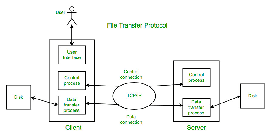
Enables users to access the network and provide services like electronic mail, file access and transfer, surfing www, etc. Communication requires two programs.

Electronic Mail

Electronic Mail is a method of exchanging messages over the internet.

  • Multimedia - text, audio, image, video (even Hyperlinks & HTML) based communication.
  • Multiple Recipients - emails can be send to many people at once using Carbon Copy (CC) and Blind Carbon Copy (BCC).
  • Encryption and Security - uses advanced security protocols like SSL/TLS.
  • Filter and sort into Folders
  • Integration with calendars, task managers, AI tools, etc.

Email is send and received using a couple different protocols.

  • SMTP is used for sending email
  • IMAP and POP3 is used for receiving email

Email basics

  1. Email address unique identifier for each user
  2. Email Client: Software program used to send, receive and message email
  3. Email Server: Computer system responsible for storing and forwarding email

Components of Email System:

  1. User Agency (UA): Program used to send, receiver, reply and read emails.
  2. Messaging Transfer Agency (MTA):
    • Transfers mail from one system to another.
    • To send a mail, a system must have both client and system MTA
    • It transfers mail to mailboxes of recipients if they share a machine
    • Delivers to main to peer MTA if destination mailbox is in another machine using Simple Mail Transfer Protocol.
  3. Mailbox: Fall on local hard drive to collect mails.

After email reaches SMTP server

  1. Server will validate the emails contents in accordance to protocol.
  2. Now server will lookup IP address of recipients email server on DNS.
  3. Now server will establish a connection, and send email is packets.
  4. Which will be re-assembled at recipients server and scan email for virus or spam.
  5. Finally server will put email to recipients mail box, for him to read.

Screenshot 2024-12-01 at 10.45.48 PM.png

POP3 vs IMAP

  • POP3 is simple. Only downloads contents on Inbox folder. While IMAP (Internet Message Access Protocol) syncs everything throughout all devices
  • POP3 offline emails on device. While IMAP keeps everything on server.
  • You can only view emails on POP3. While IMAP can also sent items, drafts, delete items, etc.

MIME - Multipurpose Internet Mail Extensions is a supplementary protocol that allows non-ASCII data to be send through email.

Web-Based Mail

  • Mail transfer from Sender's browser to her mail server is done through HTTP.
  • Transfer of message from mail server to mail server is still done through SMTP.
  • Finally message is receiver at browser via HTTP.
  • Client needs to login on website to access mail.

File Transfer Protocol (FTP)

  • Client/server protocol that allows you to transmit and receive files from a host computer.
  • FTP authentication may be done via usernames and passwords.
  • Uses PORT 20 for data and 21 for control connection.
  • Use TCP for File transfer.
  • But no encryption and no security.
  • Use SFTP for security (add a secure socket layer b/w FTP and TCP)
  • Data connection is non-persistent. Control is persistent
  • Stable

Pasted image 20250520015737.png

Control Connection
For sending control information like user identification, password, commands to change the remote directory, commands to retrieve and store files, etc., FTP makes use of a control connection. The control connection is initiated on port number 21.

Data connection For sending the actual file, FTP makes use of a data connection. A data connection is initiated on port number 20. FTP sends the control information out-of-band as it uses a separate control connection. Some protocols send their request and response header lines and the data in the same TCP connection. For this reason, they are said to send their control information in-band. HTTP and SMTP are such examples.


BS

WWW

  • World Wide Web is a distributed Client Server service.
  • Where client using a browser can access a service using server.

Browser

  • program with GUI for navigating web pages.
  • Components - controller (input - keyboard, mouse), client protocol and interpreters (display).

URL

  • Uniform Resource Locator to uniquely identify web pages.
  • Need four identifiers - Protocol (HTTP, FTP), Host (IP address), Port (pre-defined) and Path (route).

Cookie

  • Small block of data created by web server and saved on your browser for remember personal information for revisit.

HyperText Transfer Protocol: protocols used to exchange data on internet.

  • Widely used to fetch the webpages on www
  • Isn't reliable itself, but uses TCP for reliability.
  • Inband Protocol. (since data and commands transfer on the same port, unlike FTP)
  • PORT 80
  • Stateless
  • Client server architecture - uses URL
  • Media Independent
  • HTTP 1.0 Non-persistent (connection based. sessions)
  • HTTP 1.1 Persistent (connectionless. open)
  • HTTPS: added Secure Socket Layer (SSL)
  • Commands (head, get, post, put, delete, connect)

Domain Name System (DNS)

DNS is the Internet’s “phonebook.” It turns human‑friendly names (like www.example.com) into machine‑friendly IP addresses (like 93.184.216.34) so your browser can find servers.

Pasted image 20250520024131.png

DNS Hierarchy & Namespace

DNS is organized as an inverted tree of domains:

  • Root (.)
    • The invisible top‑level node.
    • Managed by root servers around the world.
  • Top‑Level Domains (TLDs)
    • Right under root:
      • Generic TLDs: .com, .org, .net, etc.
      • Country‑code TLDs: .us, .uk, .in, etc.
  • Second‑Level Domains
    • Directly under a TLD, e.g. example in example.com.
  • Subdomains
    • Further subdivisions, e.g. www (the host) in www.example.com, or mail.example.com.

How DNS Works (Resolution Process)

  1. User enters www.example.com in a browser.
  2. Cache check
    • Browser checks its own cache, then the OS cache, then the local DNS resolver (often at your ISP).
    • If the name → IP mapping is cached and unexpired, return it immediately.
  3. Recursive query to resolver
    • If not cached, the browser asks your recursive resolver to find it.
  4. Resolver queries root
    • “Who handles .com?”
    • Root server replies with a list of .com TLD servers.
  5. Resolver queries TLD server
    • “Who handles example.com?”
    • TLD server replies with the authoritative server for example.com.
  6. Resolver queries authoritative server
    • “What is www.example.com?”
    • Authoritative server returns the IP address.
  7. Resolver returns IP to the browser and caches it (for the record’s Time‑To‑Live).
  8. Browser connects to that IP to fetch the webpage.

Key DNS Server Types

  • Recursive Resolver
    • Does the full lookup on your behalf.
    • Caches responses to speed up future queries.
  • Root Name Servers
    • The starting points (“.”).
    • Know where all TLD servers live.
  • TLD Name Servers
    • Handle one TLD (like .com).
    • Point to domain’s authoritative server.
  • Authoritative Name Servers
    • Hold the actual DNS records (A, AAAA, CNAME, MX, etc.) for their domain.

Domain Name Space

  • A global, distributed database organized in that hierarchical tree.
  • Each node (domain) can have its own zone file listing subdomains and records.
  • Delegation: Parent zones delegate control of subtrees to other name servers via NS records.

More BS

Telnet

  • Telecommunication Network
  • Telnet is a network protocol that allows you to remotely connect to a computer and establish a two-way text-based communication between two computers.
  • Creates remote sessions using TCP / IP protocols, controlled by logged in user to access privileged data and applications on that computer.
  • Single operated port, hence only one connection at a time.
  • Very old technology, no encryption and low security. Replaced by SSH.
  • uses PORT 23

ARPANET

  • Created in 1969 by the Advanced Research Projects Agency (ARPA) in the U.S.
  • Aimed to connect researchers and share data.
  • Introduced packet switching (splitting data into packets to send faster and more efficiently).
  • First node-to-node communication happened in October 1969 between UCLA and Stanford.

Simple Network Management Protocol (SNMP)

  • Common tool for managing and monitoring network devices.
  • Client-server model with SNMP managers and agents.
  • Operates over UDP. (GET, SET, TRAP, etc)
  • Scalable and used for real-time monitoring.

Voice over IP

  • VoIP allows versatile communication including voice calls and multimedia over IP networks.
  • Relies of Stable Internet connection and computer hardware.
  • Susceptible to delays and security risks.

Remote Procedure Call (RPC)

Pasted image 20250520030013.png
  • Allows programs to execute procedures (functions) on a remote server, as if they were local. Facilitating Distributed computing.
  • Operates over TCP or HTTP.
  • May include authentication and encryption for security.
  • Can introduce complexities like network latency and failure handling.

Steps and Roles

  1. Client Stub Invocation
    • Client calls a local “stub” function instead of calling the remote procedure directly.
    • The stub has the same interface as the remote function.
  2. Marshaling (Packing Parameters)
    • Client Stub collects the procedure’s input parameters, serializes them into a standardized message format, and packages them for transmission.
  3. Request Transmission
    • Client sends the marshaled request over the network to the server’s RPC runtime.
  4. Unmarshaling & Server Stub Invocation
    • Server RPC runtime receives the message, passes it to the server stub, which deserializes parameters.
    • Server Stub then calls the actual procedure implementation on the server.
  5. Execution & Result Marshaling
    • Server executes the procedure with the provided arguments.
    • Server Stub marshals (serializes) the return values or exceptions into a response message.
  6. Response Transmission & Unmarshaling
    • Server RPC runtime sends the response back to the client RPC runtime.
    • Client Stub unmarshals (deserializes) the result into the client’s address space.
  7. Client Receives Result
    • Client resumes execution as if the remote call returned locally, using the unpacked result.

Firewalls

  1. Significance of Firewalls
    • Access Control: Enforce security policies by allowing/blocking traffic based on IPs, ports, protocols.
    • Threat Prevention: Stop unauthorized access, probe attempts, and certain malware from entering or leaving the network.
    • Monitoring & Logging: Record traffic patterns and suspicious activity for auditing and incident response.
  2. Types of Firewalls
    • Packet‑Filtering Firewall
      • Operates at Layer 3/4 (IP, TCP/UDP).
      • Inspects packet headers; applies rules (allow/block by source/dest IP, port).
    • Proxy (Application‑Level) Firewall
      • Acts as an intermediary at Layer 7 (HTTP, FTP, SMTP).
      • Can inspect application data (e.g., URLs, email headers) for deeper filtering.
  3. Role in Email Traffic Filtering
    • Spam Prevention:
      • Block connections from known spammer IPs (DNS-based blacklists).
      • Inspect SMTP headers/content for spam keywords or patterns.
    • Malware Defense:
      • Scan attachments for viruses, malicious macros, or payloads at the gateway before delivery.
      • Enforce content‑type restrictions (e.g., block .exe or script files).
    • Policy Enforcement:
      • Enforce Data Loss Prevention (DLP) by scanning outgoing mail for sensitive data (SSNs, credit‑card numbers).
      • Rate‑limit bulk mail to prevent compromised hosts from sending spam floods.
    • Logging & Alerts:
      • Log suspicious email attempts for forensic analysis.
      • Generate real‑time alerts on detected threats or policy violations.

Final BS

Repeater - boosts strength of signals as it travels through a communication channel. Don't interpret data.

Hub - Network hardware device to connect multiple Ethernet devices together. Sends data to all ports.

Bridge - Used to connect two different LANs. Works at Data Link Layer.

Switch - connects multiple devices on a network and uses MAC address to send data directly to the right device. Smart as sends only to specific devices.

Router - moves data between different networks, directly it based on destination information using routing table.

Gateway - Networking hardware or software for telecommunication network that allows data to flow from one discrete network to another. Can communicate using more than one protocols to connect multiple networks and can operate any of the seven layers of OSI Model.

Gateway vs. Router

AspectGatewayRouter
OSI LayerApplication / Transport (Layers 4–7)Network (Layer 3)
FunctionProtocol & data‐format translationPacket forwarding based on IP
Address TranslationYes (NAT, DHCP, etc.)Generally no (unless router also does NAT)
ComplexityHigher—may inspect and modify payloadsLower—typically handles headers only
Use CaseConnecting heterogeneous systemsLinking similar IP networks

On this page

SyllabusUnit 1Computer NetworksGoals of Computer NetworksApplications of Computer NetworksData CommunicationTransmission ModeNetwork CriteriaTypes of ConnectionPhysical TopologyMesh TopologyStar TopologyBus TopologyRing TopologyLocal Area Network (LAN)Metropolitan Area Network (MAN)Wide Area Network (WAN)OSI Model7 Layers of OSI ModelTCP/IP Model4 Layers of TCP/IP ModelProtocol Data Unit (PDU)Transmission MediaGuided Media : WiredUnguided Media: WirelessWavesSwitchingCircuit SwitchingMessage SwitchingPacket Switching1. Datagram Approach - Packet Switching2. Virtual Circuit Approach - Packet SwitchingPacket Switching TechnologyAdvantages of Packet SwitchingISDN (Integrated Services Digital Network)UNIT 2 : DATALINK LAYERMedia Access ControlRandom AccessAlohaSlotted AlohaCarrier Sense Multiple Access (CSMA)Persistence MethodCSMA with collision Detection (CSMA/CD)CSMA with Collision Avoidance (CSMA / CA)Flow and Error ControlSliding Window ProtocolStop-and-Wait ARQGo-back-N ARQSelective Repeat ARQPiggybackingTypes of ErrorsHamming distanceSimple Parity-check CodeHamming CodesChecksumCyclic Redundancy checkEthernetManchester EncodingUNIT 3 : NETWORK LAYERIPv4IPv6IPv4 vs IPv6 ComparisonAdvantages of IPv6Need of additional protocolsAddress Resolution Protocol (ARP)Reverse ARP (RARP)Internet Control Message Protocol (ICMP)1. Error Reporting2. QueryInternet Group Message Protocol (IGMP)IP AddressesNow how many devices can you host on the same network?Classes of IPv4 Address (Classful)Key FeaturesMasks in IPv4 Addressing (Subnet Mask)Default Masks for IPv4 Classes (Subnet classes)Classless Inter-Domain Routing (CIDR)RoutingUnicast Routing ProtocolsIntra-Domain RoutingInter-Domain RoutingDistance-Vector RoutingTwo-Node Instability in Distance-Vector RoutingSplit HorizonLink State RoutingUNIT 4 : TRANSPORT LAYERCongestion1. Open‑Loop (Preventive) Control2. Closed‑Loop (Reactive) Control2.1 TCP’s AIMD Algorithm2.2 TCP Phases3. SummaryTransport Layer ServiceAddressing: Port NumberTCPTCP HeaderTCP ConnectionUser Datagram Protocol (UDP)Data CompressionTypes of CompressionRun‑Length Encoding (RLE)Huffman CodingLempel–Ziv (LZ)JPEG (Joint Photographic Experts Group)MPEG (Moving Picture Experts Group)MP3 (MPEG‑1 Audio Layer III)CryptographySymmetric Key CryptographyDES (Data Encryption Standard)Asymmetric (Public‑Key) CryptographyDigital SignatureIntegrity vs. ConfidentialitySubstitution EncryptionTransposition EncryptionRSAKey GenerationEncryptionDecryptionWhy It’s SecurePutting It All TogetherUNIT 5 : APPLICATION LAYERElectronic MailEmail basicsComponents of Email System:After email reaches SMTP serverPOP3 vs IMAPFile Transfer Protocol (FTP)BSDomain Name System (DNS)DNS Hierarchy & NamespaceHow DNS Works (Resolution Process)Key DNS Server TypesDomain Name SpaceMore BSTelnetARPANETSimple Network Management Protocol (SNMP)Voice over IPRemote Procedure Call (RPC)FirewallsFinal BS