Power Plant Engineering
| Unit | Syllabus |
|---|---|
| 1 | Indian energy scenario, Indian coals: formation, properties, analysis, benefication and heating value calculation of coals; coking and non-coking coals, fuel handling systems; coal gasification. Classification of power plants, base load and Peak load power stations, co-generated power plant, captive power plant, and their fields of application & selection criteria. |
| 2 | Steam Generators: High pressure utility boiler, natural and forced circulation, coking and non-coking coal, coal benefication, coal pulverization, pulverized fuel firing system, combustion process, need of excess air, cyclone furnace, fluidized bed boiler, electrostatic precipitators and wet scrubbers, boiler efficiency calculations, water treatment. |
| 3 | Combined Cycle Power Plants: Binary vapour cycles, coupled cycles, gas turbine- steam turbine power plant, gas pipe line control, MHD-Steam power plant. |
| 4 | Other power plants: Nuclear power plants - working and types of nuclear reactors, boiling water reactor, pressurized water reactor, fast breeder reactor, controls in nuclear power plants, hydro power plant -classification and working of hydroelectric power plants, tidal power plants, diesel and gas power plants. |
| 5 | Instrumentation and Controls in power plants: Important instruments used for temperature, flow, pressure, water/steam conductivity measurement; flue gas analysis, drum level control, combustion control, super heater and re-heater temperature control, furnace safeguard and supervisory system (FSSS), auto turbine run-up system(ATRS). |
| 6 | Environment Pollution and Energy conservation: Economics of power generation: load duration curves, power plant economics, pollution from power plants, disposal/management of nuclear power plant waste, concept of energy conservation and energy auditing. |
IMPORTANT QUESTIONS - MIDSEM
1. Explain the Indian energy scenario and discuss the various factors to be considered for selection of power plants.
Indian Energy Scenario:
- Rapidly Growing Demand:
Economic growth and industrialization are driving up energy needs. - Energy Mix:
- Coal Dominance: About 70% of electricity comes from coal, due to abundant domestic reserves.
- Rising Renewables: Increased investment in solar, wind, hydro, and nuclear to diversify the mix and reduce emissions.
- Government Initiatives:
Policies like the National Solar Mission and grid modernization efforts are key to transitioning towards cleaner and more sustainable energy. - Challenges:
Balancing energy security with environmental concerns and managing fuel logistics are major issues.
Factors for the Selection of Power Plants:
- Economic Considerations:
Evaluate capital costs, operational expenses, and fuel costs/availability. The payback period and overall efficiency play crucial roles. - Technical and Operational Factors:
Consider the plant’s efficiency, reliability, and suitability for load demands (base load vs. peak load). Quick start-up and flexibility are important for peak load plants, while base load plants are designed for continuous operation. - Environmental and Regulatory Factors:
Compliance with emission standards, the overall environmental impact, and necessary permits. Cleaner technologies might have higher upfront costs but lower environmental liabilities. - Fuel and Resource Considerations:
Availability of fuel (coal, gas, renewable sources) locally, and the existing infrastructure for transportation and storage are key factors. - Strategic Considerations:
Energy security, future expansion or upgrade potential, and grid compatibility are important for long-term planning.
2. Describe the layout and working principle of a steam power plant with a neat sketch. Explain the functions of major components.
Layout and Working Principle of a Steam Power Plant
A steam power plant converts the thermal energy from fuel combustion into electrical energy through a closed-loop thermodynamic cycle (known as the Rankine cycle). The main components are arranged in a loop that continuously circulates water/steam.
Neat Sketch of a Steam Power Plant
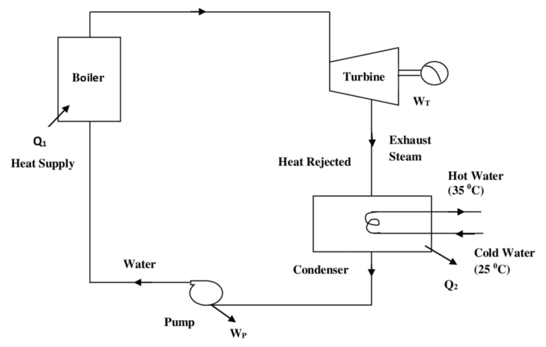
Working Principle
Heating water in a boiler to create high-pressure steam, which then expands through a turbine to generate mechanical energy that is converted into electricity by a generator; the exhausted steam is then condensed back into water and returned to the boiler to repeat the cycle, essentially using the heat energy from burning fuel to produce electricity through the expansion of steam.
Functions of Major Components
- Boiler/Furnace:
- Function: Converts water into steam by burning fuel.
- Key Elements: Economizer (preheats water), Furnace (combustion chamber), Superheater (raises steam temperature).
- Steam Turbine:
- Function: Converts the thermal energy of steam into mechanical energy by allowing the steam to expand and drive the turbine blades.
- Generator:
- Function: Transforms the mechanical energy from the turbine into electrical energy through electromagnetic induction.
- Condenser:
- Function: Cools and condenses the spent steam into water, maintaining a low-pressure environment to enhance turbine efficiency.
- Feed water Pump:
- Function: Pressurizes the condensate to push it back into the boiler, completing the cycle.
3. Compare base load and peak load power stations. Discuss their merits and demerits.
Base Load Power Stations Plants designed to run continuously, supplying a constant minimum load.
- Examples: Coal-fired, nuclear, large hydro, and combined cycle power plants.
- Merits:
- High Efficiency at Full Load: They are optimized for continuous operation, offering lower cost per unit of electricity.
- Reliability: Provide a stable, predictable supply of power essential for the grid’s minimum demand.
- Demerits:
- Inflexibility: Slow to start up or shut down, making them unsuitable for rapidly changing demand.
- High Capital Costs: Often require significant upfront investment.
Peak Load Power Stations Plants that operate only during periods of high demand or emergencies.
- Examples: Gas turbines, diesel generators, and open-cycle gas turbines.
- Merits:
- Operational Flexibility: Quick start-up and shut down, ideal for handling fluctuations in demand.
- Lower Capital Investment: Generally cheaper to build compared to base load plants.
- Demerits:
- Higher Operational Costs: They usually have lower efficiency and higher fuel costs per unit of electricity generated.
- Limited Use: Not designed for continuous operation, making them less cost-effective if run for long periods.
4. Explain the working principle of pulverized coal firing system with a neat sketch. Discuss its advantages and disadvantages.
Working Principle
- Pulverization: Coal is ground into a fine powder in a pulverizer, significantly increasing its surface area.
- Mixing with Air: The fine coal particles are mixed with preheated air in the coal-air mixer, forming a combustible mixture.
- Injection into Furnace: The coal-air mixture is injected into the boiler furnace through specially designed burners.
- Combustion: In the furnace, the finely pulverized coal ignites and burns rapidly. The high surface area ensures quick and complete combustion, releasing heat.
- Steam Generation: The heat from combustion is absorbed by water tubes within the boiler, converting water into high-pressure steam. This steam drives a turbine connected to a generator to produce electricity.
Neat Sketch

Advantages
- Efficient Combustion: Fine pulverization leads to rapid and complete combustion.
- Uniform Flame: Provides stable and uniform heat release.
- Lower Emissions: Complete combustion reduces unburnt carbon and particulate emissions.
- Quick Response: Able to adjust rapidly to changes in load demand.
- Compact Furnace Design: Faster combustion allows for smaller furnace sizes.
Disadvantages
- High Energy Consumption: Energy-intensive pulverization process.
- Maintenance Requirements: Pulverizers and burners need regular maintenance.
- Explosion Hazard: Fine coal dust increases the risk of dust explosions if not managed properly.
- Higher Capital Cost: Initial investment is higher due to specialized equipment.
- Fuel Quality Sensitivity: Performance can be affected by the coal's moisture and ash content.
5. Describe the working of a fluidized bed combustion boiler. What are its benefits over conventional boilers?
Working Principle of a Fluidized Bed Combustion Boiler
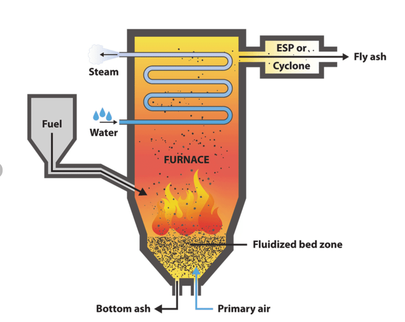
A fluidized bed combustion (FBC) boiler burns fuel in a bed of hot, inert particles (such as sand or limestone) that are suspended or “fluidized” by a stream of air. This provides excellent mixing of fuel and air, resulting in more uniform and efficient combustion.
Key Steps in the Process
- Air Distribution: Preheated air is introduced from below through a distributor plate, fluidizing the bed material and creating a turbulent, mixing environment.
- Fuel Injection: Solid fuels (coal, biomass, etc.) are fed into the fluidized bed. The fine particles of fuel mix thoroughly with the inert bed material.
- Combustion: In the fluidized state, the fuel burns at relatively low temperatures (typically around 850–900°C). The bed maintains uniform temperature, ensuring complete combustion.
- Emission Control: Limestone or other sorbents can be added to the bed to react with sulfur dioxide ( ), reducing pollutant emissions.
- Heat Transfer: Heat generated from combustion is absorbed by water tubes immersed in the bed, producing high-pressure steam for power generation.
Neat Sketch
Benefits over Conventional Boilers
- Fuel Flexibility: Can efficiently burn low-grade fuels (high moisture/ash content) and biomass, broadening fuel options.
- Lower Combustion Temperature: Operating at lower temperatures reduces formation and minimizes slagging and fouling.
- Enhanced Combustion Efficiency: Excellent mixing in the fluidized bed leads to more complete and uniform combustion.
- In-Situ Emission Control: Sorbents like limestone can be added directly into the bed to capture sulfur, reducing emissions.
- Improved Heat Transfer: The turbulent mixing ensures better heat transfer to the water tubes, improving overall efficiency.
6. Explain the Rankine cycle with relevant diagrams. How can its efficiency be improved?
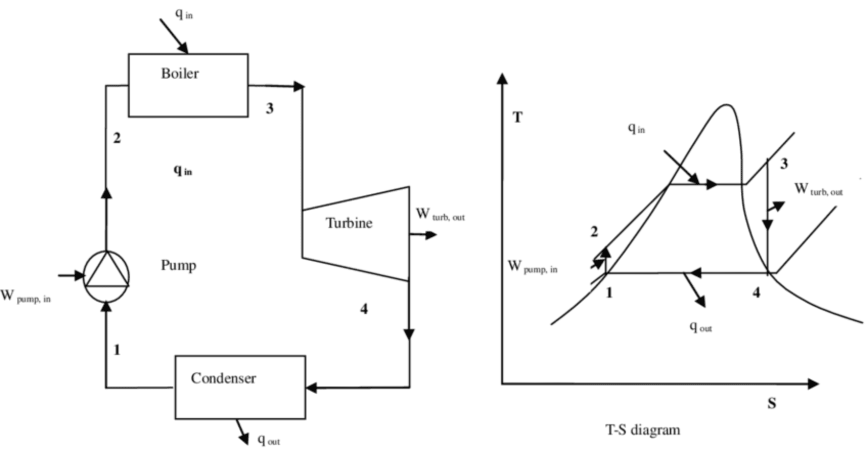
The Rankine cycle is the fundamental thermodynamic cycle used in steam power plants to convert heat energy into mechanical work, which then drives a generator to produce electricity. It involves four main processes:
- Pumping (Process 1-2): Liquid water is pressurized by a pump, raising its pressure with minimal temperature increase.
- Heat Addition in the Boiler (Process 2-3): The high-pressure water enters the boiler where it is heated at constant pressure to become high-pressure, superheated steam.
- Expansion in the Turbine (Process 3-4): The superheated steam expands through a turbine, producing work as its pressure and temperature drop.
- Condensation (Process 4-1): The low-pressure steam is condensed back into liquid water in a condenser, releasing the remaining heat to a cooling medium.
Improving the Efficiency of the Rankine Cycle
- Superheating: Increasing the temperature of the steam beyond its saturation point in the boiler increases the thermal efficiency and reduces moisture content at the turbine exit.
- Reheat Cycle: Partially expanding the steam in the turbine, then reheating it in the boiler before further expansion helps in maintaining a higher average temperature during heat addition, improving efficiency.
- Regenerative Feedwater Heating: Extracting some steam from the turbine to preheat the feedwater increases the temperature of the water entering the boiler, reducing the fuel required for heating.
- Lower Condenser Pressure: Operating the condenser at a lower pressure increases the pressure difference during expansion, thus enhancing the cycle's work output and efficiency.
- Combined Cycle: Integrating the Rankine cycle with other cycles (e.g., gas turbine cycle) can utilize waste heat, significantly boosting overall plant efficiency.
7. Discuss the effects of superheating and reheating in steam power plants.
Superheating Superheating involves heating saturated steam further in a superheater, raising its temperature above the saturation point.
- Effects:
- Increased Efficiency:
Higher temperature steam improves the thermal efficiency of the Rankine cycle. - Reduced Moisture Content:
Drier steam minimizes moisture formation in the turbine, reducing blade erosion and prolonging turbine life. - Higher Enthalpy:
Superheated steam carries more energy per unit mass, leading to greater work output during expansion.
- Increased Efficiency:
Reheating Reheating is the process of partially expanding steam in the turbine, then sending it back to the boiler to be heated again before further expansion.
- Effects:
- Enhanced Efficiency:
Maintaining a higher average temperature during expansion improves the overall cycle efficiency. - Moisture Reduction:
Reheating decreases the moisture content in the later stages of turbine expansion, further protecting turbine blades. - Increased Power Output:
The process allows for additional work extraction, leading to higher power generation. - Thermal Stress Mitigation:
Reduces the thermal gradients in the turbine, thereby lessening mechanical stress and wear.
- Enhanced Efficiency:
Both these practices help improve plant's performance, efficiency, and life.
8. Explain the working principle of combined cycle power plants. why are they becoming increasingly important?
Working Principle of Combined Cycle Power Plants A combined cycle power plant integrates two thermodynamic cycles to maximize fuel efficiency:
- Gas Turbine (Brayton Cycle):
- Process: Air is compressed, then mixed with fuel in a combustor and ignited.
- Output: The high-temperature, high-pressure gases expand in a gas turbine, generating mechanical work.
- Heat Recovery Steam Generator (HRSG):
- Process: The exhaust gases from the gas turbine, which still contain significant heat, are passed through an HRSG.
- Output: The recovered heat converts water into steam. Hence, special boilers.
- Steam Turbine (Rankine Cycle):
- Process: The steam produced in the HRSG is expanded through a steam turbine, generating additional power.
- Cycle Closure: After expansion, the steam is condensed and the water is pumped back to the HRSG, completing the cycle.
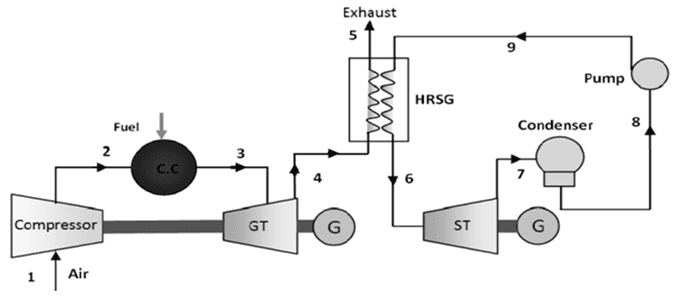
- Combustion Chamber (C.C.): burns fuel with compressed air, producing high-temperature, high-pressure gases that flow into the Gas Turbine (GT).
- Heat Recovery Steam Generator (HRSG): Waste heat from GT is used to convert water from pump to steam that flows into Steam Turbine (ST).
- Generator (G).
Why Combined Cycle Power Plants Are Becoming Increasingly Important
- High Efficiency: They achieve overall thermal efficiencies over 60% by utilizing waste heat from the gas turbine, compared to 35–40% in conventional steam plants.
- Lower Emissions: Improved efficiency means lower fuel consumption and reduced CO₂ and pollutant emissions per unit of electricity generated.
- Economic Advantages: Reduced fuel usage leads to lower operating costs and better economic viability, making them competitive in today's energy markets.
- Operational Flexibility: They can adjust power output to meet varying load demands, which is valuable for grid stability.
- Environmental and Regulatory Benefits: Their cleaner operation helps meet stringent environmental regulations, aligning with global trends toward reducing greenhouse gas emissions.
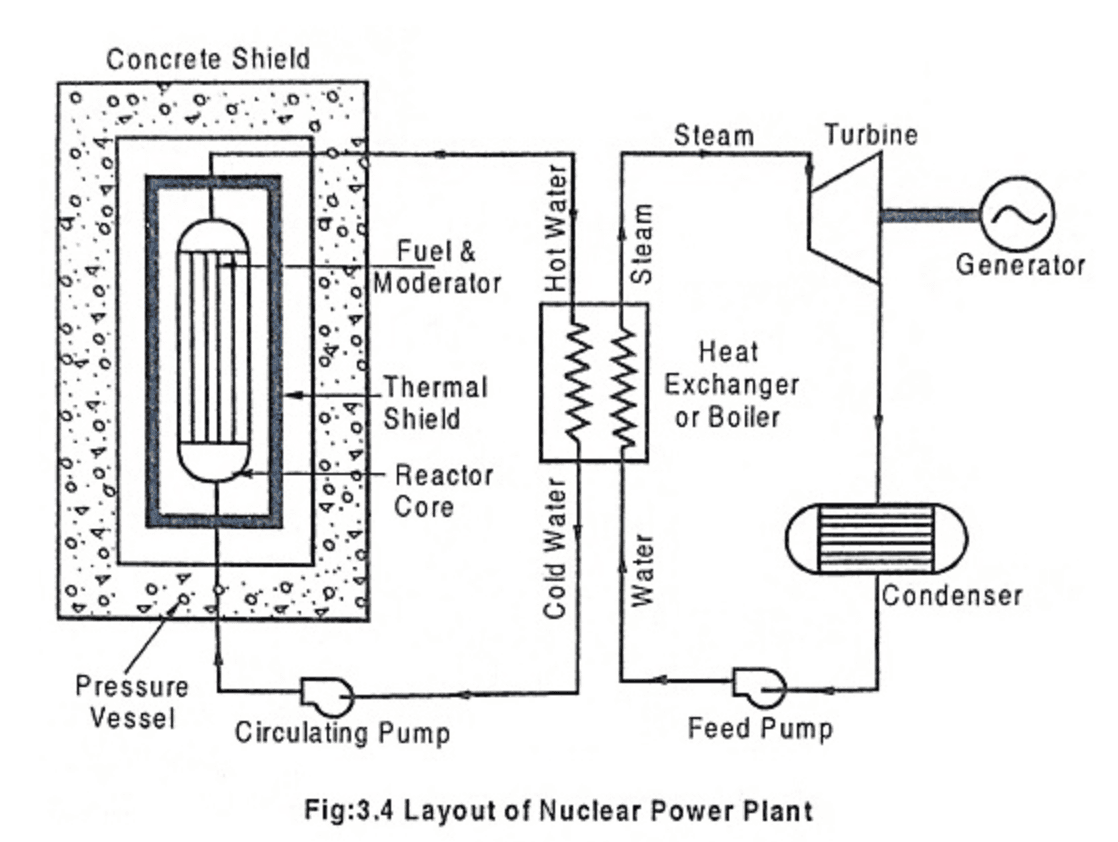
9. Describe the layout and working of a nuclear power plant. Explain the different types of nuclear reactors.
Layout and Working of a Nuclear Power Plant
- Reactor Core:
- Contains nuclear fuel (usually uranium or plutonium) arranged in fuel assemblies.
- Control rods (made of neutron-absorbing materials) are inserted/withdrawn to control the fission chain reaction.
- The core is moderated (using water or heavy water) to slow down neutrons for sustained fission.
- Coolant System:
- A coolant (typically water, heavy water, or liquid metal) circulates through the reactor core to absorb the heat produced by fission.
- Heat Transfer:
- In PWRs: The hot primary coolant transfers its heat to a secondary water circuit via a steam generator without direct contact.
- In BWRs: Water in the reactor is allowed to boil; the generated steam directly drives the turbine.
- Turbine and Generator:
- The steam produced drives a turbine connected to a generator, converting thermal energy into electrical energy.
- Condenser and Feedwater System:
- After passing through the turbine, the steam is condensed back into water in a condenser.
- The condensate is then pumped back to the steam generator or reactor, completing the cycle.
- Containment Structure:
- A robust, airtight structure encloses the reactor and associated systems to prevent any release of radioactivity.
Different Types of Nuclear Reactors
- Pressurized Water Reactor (PWR):
- Coolant/Moderator: Light water maintained under high pressure.
- Operation: Water in the primary loop is kept from boiling; heat is transferred to a secondary loop in a steam generator.
- Usage: Most common reactor type globally.
- Boiling Water Reactor (BWR):
- Coolant/Moderator: Light water that boils directly in the reactor vessel.
- Operation: The generated steam is directly used to drive the turbine, eliminating the need for a separate steam generator.
- Pressurized Heavy Water Reactor (PHWR/CANDU):
- Coolant/Moderator: Heavy water (D₂O).
- Operation: Uses natural uranium as fuel; offers on-line refuelling and greater fuel flexibility.
- Fast Breeder Reactor (FBR):
- Coolant: Often uses liquid metal (e.g., sodium) instead of water.
- Operation: Uses fast neutrons to convert fertile material (like uranium-238) into fissile material (plutonium-239), generating more fuel than consumed.
- Advanced Gas-Cooled Reactor (AGR):
- Coolant/Moderator: Carbon dioxide as coolant and graphite as moderator.
- Operation: Uses uranium dioxide fuel in pressure tubes; primarily found in the United Kingdom.
10. Calculate efficiency, work output, or heat rates for given steam cycle parameters (numerical problem).
Basic Theory
- Rankine Cycle Overview:
- The Rankine cycle is used in steam power plants to convert heat into work (electricity).
- Key components include a boiler (where water is turned into steam), a turbine (where steam expands to produce work), a condenser (where steam is turned back into water), and a pump (to recycle the water).
- In many exam problems, the pump work is considered negligible.
- Isentropic Expansion:
- When steam expands in the turbine, the process is often assumed to be isentropic (i.e., the entropy remains constant).
- This helps us find the quality of steam (the ratio of vapor to total mass) at the turbine exit using the steam table values.
Key Formulas and Their Meanings
Turbine Work Output:
- Formula:
- Explanation: is the enthalpy of steam at the turbine inlet, and is the enthalpy at the turbine exit. Their difference represents the energy converted to work.
Heat Input:
- Formula:
- Explanation: is the steam enthalpy coming out of the boiler, and is the enthalpy of water entering the boiler. This difference is the energy added to the cycle.
Thermal Efficiency:
- Formula:
- Explanation: The efficiency is the ratio of the net work output (usually taken as the turbine work when pump work is negligible) to the heat input.
Heat Rate:
- Formula:
- Explanation: This shows how much heat energy is required to produce one unit of electrical energy. The multiplication by 3600 converts the units from kJ per kJ to kJ per kWh.
Determining Steam Quality (for Isentropic Expansion):
- Formula:
- Explanation: Here, is the entropy at the turbine inlet, and are the entropies of the saturated liquid and vapor at the turbine exit pressure, and is the steam quality (fraction of vapor). Once is known, you can find using:
Sample Problem
A simple Rankine cycle operates under the following conditions:
- Boiler (State 1): Steam is generated at 10 MPa and 600°C.
- Turbine Exit (State 2): Steam expands isentropically to 0.1 MPa.
- Assumption: Pump work is negligible.
Using approximate steam table data:
- At 10 MPa and 600°C:
- At 0.1 MPa (saturated conditions):
- Saturated liquid enthalpy,
- Saturated vapor enthalpy,
- Saturated liquid entropy,
- Saturated vapor entropy,
Tasks:
- Determine the turbine exit enthalpy .
- Calculate the net work output per kg of steam.
- Compute the thermal efficiency of the cycle.
- Determine the heat rate (in kJ/kWh).
Step-by-Step Solution
1. Turbine Expansion (State 1 to State 2)
Since the expansion is isentropic:
At 0.1 MPa, let the quality of the steam be . Then:
Solving for :
x = \frac{s_1 - s_f}{s_g - s_f} = \frac{6.50 - 1.10}{7.50 - 1.10} = \frac{5.40}{6.40} \approx 0.844Now, determine the enthalpy at turbine exit :
Substitute the values:
h_2 = 417 + 0.844 \times 2167 \approx 417 + 1828 \approx 2245\ \text{kJ/kg}2. Turbine Work Output
Turbine work per kg of steam is given by:
W_{\text{turbine}} = h_1 - h_2 = 3580 - 2245 \approx 1335\ \text{kJ/kg}3. Heat Input and Thermal Efficiency
Assuming the feedwater enters the boiler at nearly the condensate condition , the heat input is:
Q_{\text{in}} = h_1 - h_{\text{feedwater}} = 3580 - 417 = 3163\ \text{kJ/kg}Thermal efficiency is:
\eta = \frac{W_{\text{net}}}{Q_{\text{in}}} \approx \frac{1335}{3163} \approx 0.422\ \text{or}\ 42.2\%4. Heat Rate
Heat rate is the amount of heat input required per unit of work output. In kJ per kWh, it is calculated as:
Result
- Turbine Exit Enthalpy : ~2245 kJ/kg
- Net Work Output: ~1335 kJ/kg
- Thermal Efficiency: ~42.2%
- Heat Rate: ~8532 kJ/kWh
11. Fuel Handling System
- Fuel Storage: The starting point where fuel is stored.
- Fuel Handling/Feeding: Prepares the fuel by conditioning and sizing it.
- Conveying System: Transports the fuel to the processing stage.
- Pulverizing/Crushing Unit: Processes the fuel (especially coal) into a fine powder.
- Boiler Furnace Feeding: Delivers the processed fuel into the furnace.
- Combustion Process: The fuel is burned to produce steam.
- Ash Handling: Manages the residual ash produced from combustion.
IMPORTANT QUESTIONS - ENDSEM
1. Briefly explain coal beneficiation processes. Also mention it's advantage.
Coal beneficiation (also called coal preparation or coal washing) involves removing impurities and improving the quality of raw coal. The main processes are:

- Crushing & Screening
- Crushing: Reduces coal to manageable sizes (e.g. < 50 mm).
- Screening: Sorts crushed coal into different size fractions for targeted cleaning.
- Density Separation
- Heavy-Medium Cyclones: Coal and inert material are separated by their differing buoyancy in a dense liquid medium (e.g. magnetite slurry); lighter coal floats, heavier ash-formers sink.
- Jigs: Pulsating water currents stratify particles by density; clean coal is drawn off the top.
- Flotation
- Fine coal (< 0.5 mm) is mixed with water and flotation reagents; hydrophobic coal particles attach to air bubbles and rise, while hydrophilic impurities remain in the water.
- Dewatering & Drying
- Removes excess water from washed coal via centrifuges, filters or thermal drying to meet moisture specifications for transport and combustion.
Advantage of Coal Beneficiation
- Improved Fuel Quality: Raises calorific (heating) value by reducing ash and moisture.
- Reduced Emissions: Lower ash and sulfur content lead to fewer particulate and SO₂ emissions during combustion.
- Economic Benefits: Lighter, higher-grade coal lowers transportation costs per unit energy and commands better market prices.
- Environmental Compliance: Helps meet regulatory limits on ash, sulfur, and other pollutants from coal-fired power plants.
2. Describe fuel handling system in power plant with flow chart.
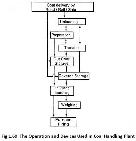
- Unload
- Feed
- Crushing
- Screening
- Convey
- Store
- Weigh
- Magnetic Separate
- Dust
- Boiler
MHD
A Magnetohydrodynamic (MHD) Combined Cycle Power Plant is an advanced power generation system that combines direct conversion of plasma energy to electricity (via an MHD generator) with a conventional steam cycle to enhance overall efficiency.
🔧 Working Principle (Step-by-step Explanation):
Refer to the diagram above for component-wise flow:
1. Combustion Chamber
-
Fuel (usually coal or natural gas) is burned with oxygen-enriched air.
-
A seeding material like potassium carbonate is added to make the combustion gases electrically conductive (ionized gas or plasma).
2. MHD Generator
-
The ionized gas flows at high speed through a magnetic field.
-
Due to Faraday’s law, a voltage is induced perpendicular to both gas flow and magnetic field.
-
Electrodes extract direct current (DC) electricity.
-
Very high exhaust temperatures remain (2000–3000 K).
3. Heat Recovery – Combined Cycle Section
-
The hot gases exiting the MHD generator enter a heat exchanger or Heat Recovery Steam Generator (HRSG).
-
This heats water into steam, which drives a conventional steam turbine to produce additional power (AC output).
-
The gases are then cooled further before being released or reused.
4. Steam Turbine Generator
-
Operates like a regular Rankine cycle.
-
Produces additional electricity, typically alternating current (AC), improving overall plant efficiency.
5. Auxiliary Systems
-
Air preheaters and compressors improve combustion efficiency and gas flow.
-
A converter (inverter/rectifier) is needed to interface DC output from the MHD generator with the grid (usually AC).
⚡ Advantages
-
Higher Efficiency: Can exceed 50% overall by combining MHD (~20%) and steam (~30%) cycles.
-
Fast Response: Direct conversion is rapid, useful for load-following.
-
Reduced Moving Parts: The MHD generator has no mechanical rotor.
⚠️ Challenges
-
High operating temperatures and plasma chemistry require exotic materials and complex cooling.
-
Electrodes suffer from erosion and plasma corrosion.
-
Still largely experimental or pilot-scale; not widely commercialized.
Would you like a breakdown of efficiency comparisons or real-world examples of MHD pilot plants?
PWR

1. Primary (Reactor) Loop
-
Reactor Vessel
-
Fuel assemblies (uranium fuel rods) generate heat via nuclear fission.
-
Coolant: High-pressure water circulates through the core, removing heat.
-
Pressure: Typically ~155 bar (2,250 psi) to keep water liquid at ~300 °C.
-
-
Pressurizer
-
A vertical, partially-filled surge tank connected to the top of the reactor loop.
-
Heaters at the bottom and a spray system at the top maintain pressure control:
-
Increase Pressure: Electric heaters boil additional water into steam, raising system pressure.
-
Decrease Pressure: Cooler water spray condenses steam, lowering pressure.
-
-
Function: Keeps reactor-coolant pressure within safe limits to prevent boiling in the core.
-
-
Hot Leg and Steam Generator Inlet
- Heated primary water exits the reactor (“hot leg”) and flows into the steam generator tubes.
2. Steam Generator (Heat Exchanger)
-
Primary Side (inside tubes): Still-pressurized water at ~300 °C transfers heat to the secondary side.
-
Secondary Side (shell side): Lower-pressure feedwater flashes to steam (~75–100 bar, ~275 °C) without mixing with the radioactive primary water.
3. Secondary (Turbine) Loop
-
Steam Turbine
- High-pressure steam from the steam generator expands through the turbine, producing mechanical shaft power.
-
Electric Generator
- Coupled to the turbine, converts mechanical rotation into electricity for the grid.
-
Condenser & Feedwater Pump
-
Exhaust steam condenses back to water in the condenser (cooled by an external water source).
-
Feedwater pump raises condensate back to steam-generator pressure (~75–100 bar) and returns it to the steam generator.
-
4. Pressurizer: Why It’s Crucial
-
Boiling Prevention: By keeping the primary water under high pressure, the pressurizer ensures no phase change (boiling) occurs in the reactor core, which could compromise cooling and neutron moderation.
-
Pressure Control: Reactors undergo power changes (startup, load-following, shutdown) that affect temperature and thus pressure. The pressurizer’s heaters and spray system quickly adjust steam volume to stabilize the loop pressure.
-
Safety Margin: A controlled “steam bubble” in the pressurizer provides a buffer against pressure transients, preventing over-pressure trips or under-pressure conditions.
List of the principal methods used in utility boilers to control superheat steam temperature:
-
Desuperheating (Attemperation) by Water Injection
-
Desuperheating by Saturated-Steam Injection
-
Flue-Gas Bypass (Gas-Side Control)
-
Steam Bypass (Steam-Side Control)
-
Varying Gas Flow through Final Superheater Banks
Method 1: Water-Spray Attemperator
Principle:
A fine spray of de-mineralized water is injected into the hot superheated steam; the water evaporates instantly, absorbing the excess heat and “stepping down” the steam temperature to the setpoint.
    ┌───────────┐   ┌────────────────┐   ┌─────────┐
	│ Final     │──▶│ Attemperator   │──▶│ Turbine │
	│Superheater│   │ (Water Nozzle) │   └─────────┘
    └───────────┘   └──────┬─────────┘
                           │
Control Valve───┴───► Water Spray- Control loop: A thermocouple at the attemperator outlet feeds a PID controller, which modulates the water-spray valve to maintain the desired °C.
- Advantages: Fast response, precise temperature trimming, simple retrofit.
- Considerations: Water must be ultra-pure to avoid tube corrosion and carry-over.
Method 2: Flue-Gas Bypass Damper
Principle:
Part of the hot flue-gas stream is diverted around (i.e. bypasses) the final superheater bank. By throttling a damper in the bypass duct, the mass-flow (and thus heat transfer) through the superheater can be reduced, lowering steam temperature.
  [ Boiler ]────▶┌─────────────┐────▶ Superheater ──▶ Turbine
                 │             │
                 │  Bypass     │
                 │  Duct       │
                 └─┬───▶▼───┬───┘
                   ▲ Damper ─┘
                   │
Flue Gas-
Control loop: A temperature sensor downstream of the SH outlet drives a PID that adjusts the bypass-damper position.
-
Advantages: No water handling, no risk of carry-over, fully steam-side dry.
-
Considerations: Requires ducting space and precise damper control; slower response than spray.
Explain with schematic diagram, combustion control in the furnace.
Combustion control in a furnace is essential for achieving optimal fuel efficiency, reducing emissions, and maintaining safe operation. It involves regulating the air-fuel mixture to ensure complete and efficient combustion.
🔥 1. Purpose of Combustion Control:
- Maintain correct air-to-fuel ratio.
- Maximize combustion efficiency.
- Minimize pollutants (CO, NOx, unburnt fuel).
- Adjust to load demand variations.
⚙️ 2. Basic Components of Combustion Control System:
- Fuel Flow Control Valve – Regulates the amount of fuel entering the burner.
- Air Flow Control Valve/Damper – Controls the volume of air (especially oxygen) for combustion.
- Flow Transmitters – Measure fuel and air flow rates.
- O2/CO Analyzers – Monitor flue gas composition for excess oxygen or carbon monoxide.
- Controllers (PID Loop) – Compare actual values with setpoints and adjust accordingly.
- Burner Management System (BMS) – Ensures safe burner startup/shutdown and flame monitoring.
🔄 3. Types of Combustion Control Systems:
a. Single-Point Positioning (Jackshaft System):
- One actuator controls both air and fuel valves.
- Simple, low-cost, but less accurate.
b. Parallel Positioning:
- Separate actuators for fuel and air, driven by a common controller.
- More flexible and accurate.
c. Cross-Limiting (Lead-Lag) Control:
-
Uses two PID controllers with a logic system:
- Air leads when load increases.
- Fuel leads when load decreases.
-
Prevents fuel-rich conditions and ensures safety.
d. O2 Trim Control:
- Fine-tunes air flow based on oxygen sensor in flue gas.
- Improves efficiency and adapts to fuel quality changes.
✅ 4. Benefits of Good Combustion Control:
- Reduced fuel consumption.
- Lower emissions.
- Safer operation.
- Prolonged equipment life.
Air Pollution from Coal-Based Thermal Power Plants
Coal-fired power plants are major sources of air pollutants—both criteria pollutants and greenhouse gases. Their emissions arise primarily from the combustion of pulverized coal in boilers to generate steam. Below is a structured discussion:
1. Major Pollutants and Their Formation
| Pollutant | Formation Mechanism | Typical Emissions Range |
|---|---|---|
| Sulfur Oxides (SO₂) | Oxidation of sulfur inherent in coal (≈0.5–3 % by weight). | 500–2,000 mg/Nm³ |
| Nitrogen Oxides (NOₓ) | Thermal NOₓ (from N₂/O₂ at high flame temperatures) and fuel NOₓ (from nitrogen in coal). | 200–700 mg/Nm³ |
| Particulate Matter (PM₂.₅/PM₁₀) | Fly ash and unburned carbon entrained in flue gas. | 50–300 mg/Nm³ |
| Mercury & Heavy Metals | Trace metals vaporize and later condense on particulates. | μg/Nm³ levels |
| Carbon Monoxide (CO) | Incomplete combustion in local fuel-rich pockets. | 5–50 mg/Nm³ |
| Greenhouse Gas (CO₂) | Complete combustion of carbon in coal. | 800–1,200 g/kWh |
2. Environmental and Health Impacts
-
Sulfur Oxides (SO₂):
-
Reacts in atmosphere to form sulfuric acid—acid rain, which damages forests, soils, and aquatic ecosystems.
-
Irritates respiratory airways; aggravates asthma and bronchitis.
-
-
Nitrogen Oxides (NOₓ):
-
Precursor to tropospheric ozone and photochemical smog.
-
Forms nitric acid—contributes to acid rain.
-
Causes respiratory inflammation; reduces lung function.
-
-
Particulate Matter (PM):
-
Fine particles penetrate deep into lungs and bloodstream.
-
Linked to cardiovascular disease, lung cancer, and premature mortality.
-
-
Mercury & Heavy Metals:
-
Mercury bioaccumulates in fish; neurotoxic effects on humans (especially fetuses and young children).
-
Other metals (arsenic, lead) also pose neurological and carcinogenic risks.
-
-
CO and CO₂:
-
CO binds with hemoglobin, reducing oxygen transport.
-
CO₂ is the principal anthropogenic greenhouse gas driving climate change.
-
3. Pollution Control Measures
| Pollutant | Control Technology | Removal Efficiency |
|---|---|---|
| SO₂ | Flue-Gas Desulfurization (FGD) – wet limestone scrubbers | 90–98 % |
| NOₓ | Low-NOₓ burners, Selective Catalytic Reduction (SCR), Selective Non-Catalytic Reduction (SNCR) | 50–90 % (SCR) |
| PM | Electrostatic Precipitators (ESP), Fabric Filters (Baghouses) | 99 %+ |
| Mercury | Activated carbon injection, Hg-specific catalysts | 70–95 % (with co-benefit from PM controls) |
| CO | Optimized combustion controls, adequate air staging | 50–90 % |
4. Regulatory Standards and Trends
-
Emission Limits: Many countries cap stack emissions—e.g., SO₂ < 200 mg/Nm³; NOₓ < 200 mg/Nm³; PM < 50 mg/Nm³.
-
Mercury Rules: Stringent mercury emission standards (e.g., < 0.03 mg/Nm³ in the U.S.).
-
Shift to Cleaner Fuels: Co-firing with biomass or natural gas to lower carbon intensity.
-
Carbon Capture: Emerging CCS (carbon capture and storage) to curb CO₂ emissions, though currently limited by cost and infrastructure.
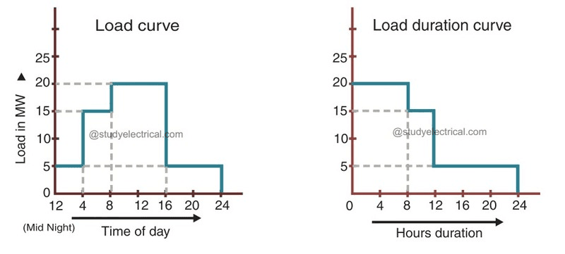
Load Demand Curve
Construction of a Load-Duration Curve
A load-duration curve (LDC) provides a clear picture of how an electrical load varies over a specified period (typically one year). To construct it, follow these steps:
-
Data Collection
- Record the system (or plant) load at regular intervals (e.g., hourly) over the chosen period.
- You’ll end up with N data points, where N = (number of days) × (24 hours/day), if hourly.
-
Sorting the Loads
- Arrange all NN load values in descending order (from highest to lowest).
- Label them .
-
Assigning Time-Fractions
- For each ordered load LiL_i, compute its corresponding percentage of time:
- Here, t1t_1 is the fraction of the period during which the load is at or above L1L_1, etc.
- Plotting the Curve
- On the vertical axis (ordinate), plot load in MW (or kW).
- On the horizontal axis (abscissa), plot cumulative time percentage tit_i from 0 % to 100 %.
- Connect the points (ti,Li)(t_i, L_i) to form a non-increasing curve.
Result: The load-duration curve starts at the maximum observed load (at 0 % time) and gently slopes down to the minimum load (at 100 % time).
Significance of the Load-Duration Curve
-
Generation Planning & Sizing
-
Base-Load Plants: Identify the “flat” upper portion of the curve that persists for a large fraction of time—ideal for economical, continuous-operation units (e.g., coal, nuclear).
-
Peaking Plants: The steep tail (right end) at low durations marks the highest peaks—suited for fast-starting, expensive units (e.g., gas turbines).
-
-
Load Factor & Utilization
-
Load Factor = (Average Load) / (Peak Load).
-
On the LDC, the area under the curve represents total energy; comparing this to a rectangle at peak load yields the load factor, a key efficiency metric.
-
-
Economic Dispatch & Tariff Design
-
Helps determine generation mix to minimize fuel costs.
-
Guides time-of-use or demand-charge tariff structures by showing how often high loads occur.
-
-
Reliability & Reserve Margin
- By examining the curve’s steepness, planners assess how sharply demand can rise, informing reserve requirements and spinning-reserve capacities.
-
Maintenance Scheduling
- Maintenance for base-load units can be timed during low-load periods (toward the right), minimizing impact on system adequacy.
-
Investment Decisions
-
Long-term: Sizing new plants, evaluating renewables integration (e.g., match solar output to daytime load-duration shape).
-
Short-term: Deciding when to call on demand-response or storage assets.
-
In Summary
The load-duration curve distills vast load-time data into a simple, powerful tool. By re-ordering load data by magnitude rather than sequence, it reveals how often (and how long) different load levels occur—directly informing generation mix, economic dispatch, tariff design, and reliability planning.
Short Notes
(a) Electrostatic Precipitator (ESP)
-
Purpose: Remove fine ash particles (fly-ash) from flue gases before they exit the stack.
-
Principle: Charged-particle collection by electrostatic attraction.
-
How it works:
-
Charging Section: Flue gas flows between discharge electrodes (thin wires) and grounded collecting plates. A high-voltage field ionizes the gas and imparts a negative charge to ash particles.
-
Collection Section: Charged particles migrate to—and stick on—the grounded plates.
-
Rapping/Cleaning: Periodically, mechanical raps shake the plates so ash falls into hoppers below.
-
-
Key Benefits:
-
≥99% removal efficiency for submicron particles
-
Low pressure-drop → minimal fan-power penalty
-
Handles high temperatures and large gas volumes
-
(b) Superheaters
-
Purpose: Increase steam temperature above its saturation (boiling) point—“dry” steam boosts turbine efficiency and protects blades.
-
Types:
-
Radiant Superheater: Closest to the furnace; absorbs heat by radiation.
-
Convection Superheater: In the gas-pass section; absorbs heat by convection.
-
-
Operation: Saturated steam from the boiler drum passes through superheater tubes, where it picks up extra heat before going to the turbine.
-
Benefits:
-
Improves Rankine-cycle efficiency by several percentage points
-
Eliminates moisture in steam → reduces turbine blade erosion
-
(c) Energy Audit
-
Definition: A systematic inspection and analysis of energy flows in a building, process, or system—to identify savings opportunities.
-
Main Steps:
-
Pre-audit (Planning): Gather utility bills, equipment lists, operating schedules.
-
On-site Audit: Measure energy consumption (meters, data loggers), inspect equipment, interview staff.
-
Analysis: Compare actual performance to benchmarks; calculate savings from possible improvements (e.g., lighting retrofit, boiler tuning).
-
Report & Recommendations: List measures ranked by payback, cost, and feasibility.
-
-
Goal: Reduce energy use, cut costs, and lower environmental impact.
(d) Combined Cycle Gas Turbine Power Plant (CCGT)
-
Concept: Combine a gas turbine cycle and a steam turbine cycle into one plant—using waste heat from the gas turbine to generate additional power.
-
Major Components:
-
Gas Turbine (Brayton Cycle): Air compressor → combustion chamber → gas turbine → generates power and hot exhaust gases.
-
Heat Recovery Steam Generator (HRSG): Captures exhaust heat to produce steam.
-
Steam Turbine (Rankine Cycle): Steam expands through turbine, producing extra electricity.
-
-
Advantages:
-
High Efficiency: Up to ~60% (vs. ~35–40% for simple cycles)
-
Lower Emissions: Burns natural gas cleanly; uses waste heat
-
Flexibility: Fast start-up and load-following capabilities
-